Unlock instant, AI-driven research and patent intelligence for your innovation.

Pulse extension circuits for extending pulse signals

Inactive Publication Date: 2008-09-02
NOVATEK MICROELECTRONICS CORP
View PDF6 Cites 4 Cited by
  • Summary
  • Abstract
  • Description
  • Claims
  • Application Information

AI Technical Summary

Benefits of technology

[0010]The present invention discloses a pulse extension circuit for extending a pulse signal. The pulse extension circuit comprises an input unit for receiving the pulse signal; an edge detection unit coupled to the input unit for generating a initiation signal according to the pulse signal; a pulse initiation unit coupled to the edge detection unit for outputting a control signal and for adjusting a voltage level of the control signal according to the initiation signal and a first reset signal; a pulse width control unit coupled to the pulse initiation unit for outputting a termination

Problems solved by technology

However, if the inputted pulse signal is too short, for instance, if the inputted pulse signal is shorter than a period of a clock signal, the flip-flop circuits cannot sample such short pulse signals according to the clock signal, so that a desired pulse extension signal cannot be generated.
However, when the pulse signal is too short, such as the pulse signal initiating and terminating between the timing points T0 and T1 in FIG. 2, the first D-type flip-flop D1 cannot sample the pulse signal according to the clock signal, so that the pulse extension circuit 10 loses its efficacy.
As mentioned above, the prior art pulse extension circuit directly extends the inputted pulse signal, but if the inputted pulse signal is too short, the desired pulse extension signal cannot be generated accordingly.

Method used


Image

  • Pulse extension circuits for extending pulse signals
  • Pulse extension circuits for extending pulse signals
  • Pulse extension circuits for extending pulse signals

Examples


Embodiment Construction

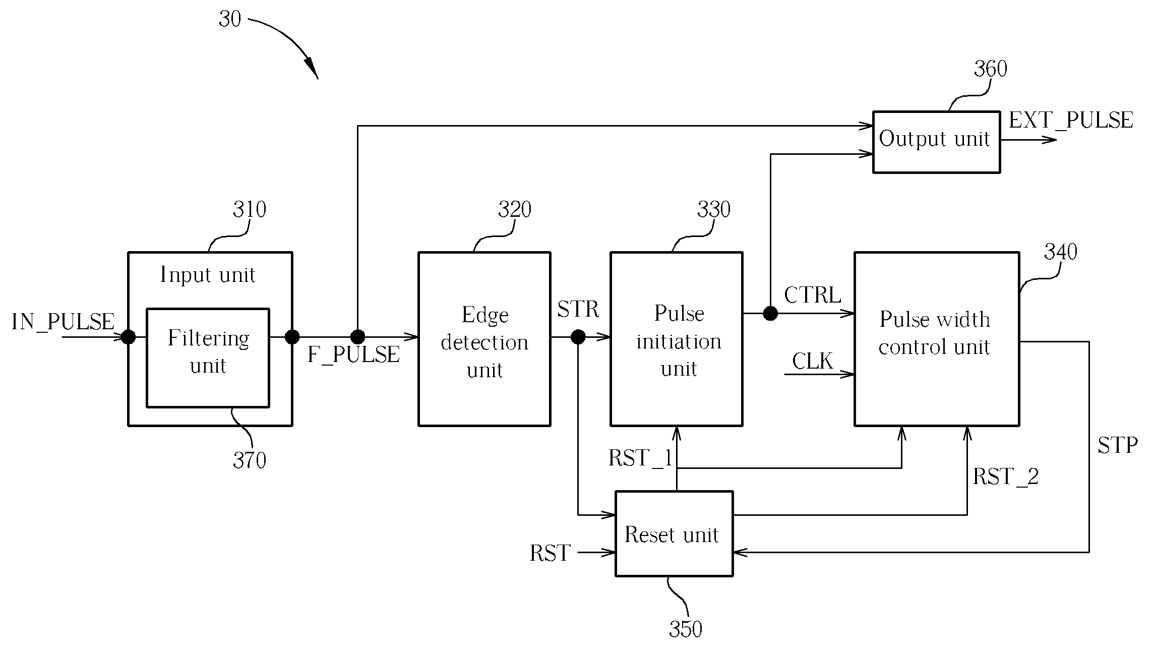
[0022]Please refer to FIG. 3. FIG. 3 is a function block diagram of a pulse extension circuit 30 according to the present invention. The pulse extension circuit 30 includes an input unit 310, an edge detection unit 320, a pulse initiation unit 330, a pulse width control unit 340, a reset unit 350 and an output unit 360. The input unit 310 is utilized for receiving a pulse signal IN_PULSE, and includes a filtering unit 370. The filtering unit 370 is utilized for filtering noises of the pulse signal IN_PULSE and generating a pulse signal F_PULSE. The edge detection unit 320 is coupled to the input unit 310, and is utilized for generating an initiation signal STR according to the pulse signal F_PULSE. The pulse initiation unit 330 coupled to the edge detection unit 320 is utilized for outputting a control signal CTRL and for adjusting a voltage level of the control signal CTRL according to the initiation signal STR and a first reset signal RST_1 outputted by the reset unit 350. The pul...


PUM


Abstract

A pulse extension circuit for extending a pulse signal includes an input unit for receiving the pulse signal, an edge detection unit coupled to the input unit for generating a initiation signal, a pulse initiation unit coupled to the edge detection unit for outputting a control signal and adjusting a voltage level of the control signal, a pulse width control unit coupled to the pulse initiation unit for outputting a termination signal, a reset unit coupled to the edge detection unit, the pulse initiation unit and the pulse width control unit for outputting the first reset signal and the second reset signal to reset the pulse initiation unit and the pulse width control unit, and an output unit coupled to the input unit and the pulse initiation unit for extending a signal period of the pulse signal according to the pulse signal and the control signal.

Description

BACKGROUND OF THE INVENTION[0001]1. Field of the Invention[0002]The present invention relates to a pulse extension circuit for extending a pulse signal, and more particularly, to a pulse extension circuit for controlling a pulse extension signal by an initiation signal and a termination signal.[0003]2. Description of the Prior Art[0004]In the prior art, a pulse extension circuit for extending pulse signals utilizes serialized flip-flop circuits for extending the inputted pulse signals. However, if the inputted pulse signal is too short, for instance, if the inputted pulse signal is shorter than a period of a clock signal, the flip-flop circuits cannot sample such short pulse signals according to the clock signal, so that a desired pulse extension signal cannot be generated.[0005]Please refer to FIG. 1. FIG. 1 is a schematic diagram of a prior art pulse extension circuit 10. The pulse extension circuit 10 includes D-type flip-flops D1˜Dn and an OR gate 110. Each D-type flip-flop incl...

Claims


Application Information

Patent Timeline
IPC IPC(8): H03K3/017
CPCH03K5/05
Inventor TUNG, CHIA-HSINHSU, LIANG-KUEI
Owner NOVATEK MICROELECTRONICS CORP