Powershift gearbox for construction machines, especially for a tractor backhoe loader and a telescopic handler

a technology for construction machines and gearboxes, which is applied in fluid gearings, transportation and packaging, and gearings, etc., can solve the problems of large lateral misalignment of output, inability to adapt to the needs of different axle bases, and inability to adapt to different axle bases in unfavorable ways

Active Publication Date: 2008-09-09
ZF FRIEDRICHSHAFEN AG
View PDF15 Cites 8 Cited by
  • Summary
  • Abstract
  • Description
  • Claims
  • Application Information

AI Technical Summary

Benefits of technology

[0021]The position of the front wheel drive can be arranged variably in accordance with this invention, since the front wheel drive in a large angle window can be arranged around the output. For an excavator loader front wheel drive can be variable inserted. For a telescopic handler transmission, the output is united to the rear and forward in a shaft.

Problems solved by technology

For example, the available fitting space, if it is extremely small, can fail.
In many cases, for example, a large lateral misalignment of the output is necessary for drive.
With the transmission concepts being the state of the art, the axle base cannot variably be arranged in an unfavorable way.
The existing kinematic diagrams exhibit the disadvantage that the outward transmission is only conditionally, flexibly shaped.
Thus it is often impossible to satisfy a transmission concept of the requirements to the fitting space of the various types of motor vehicles.
Moreover, many of the usual kinds of transmissions do not exhibit the necessary flexibility, especially modularity, in order to correct the different requirements of the numbers of threads in a transmission concept.
For the realization of these different numbers of threads, at least often complex re-designs are necessary.

Method used


Image

  • Powershift gearbox for construction machines, especially for a tractor backhoe loader and a telescopic handler
  • Powershift gearbox for construction machines, especially for a tractor backhoe loader and a telescopic handler
  • Powershift gearbox for construction machines, especially for a tractor backhoe loader and a telescopic handler

Examples


Embodiment Construction

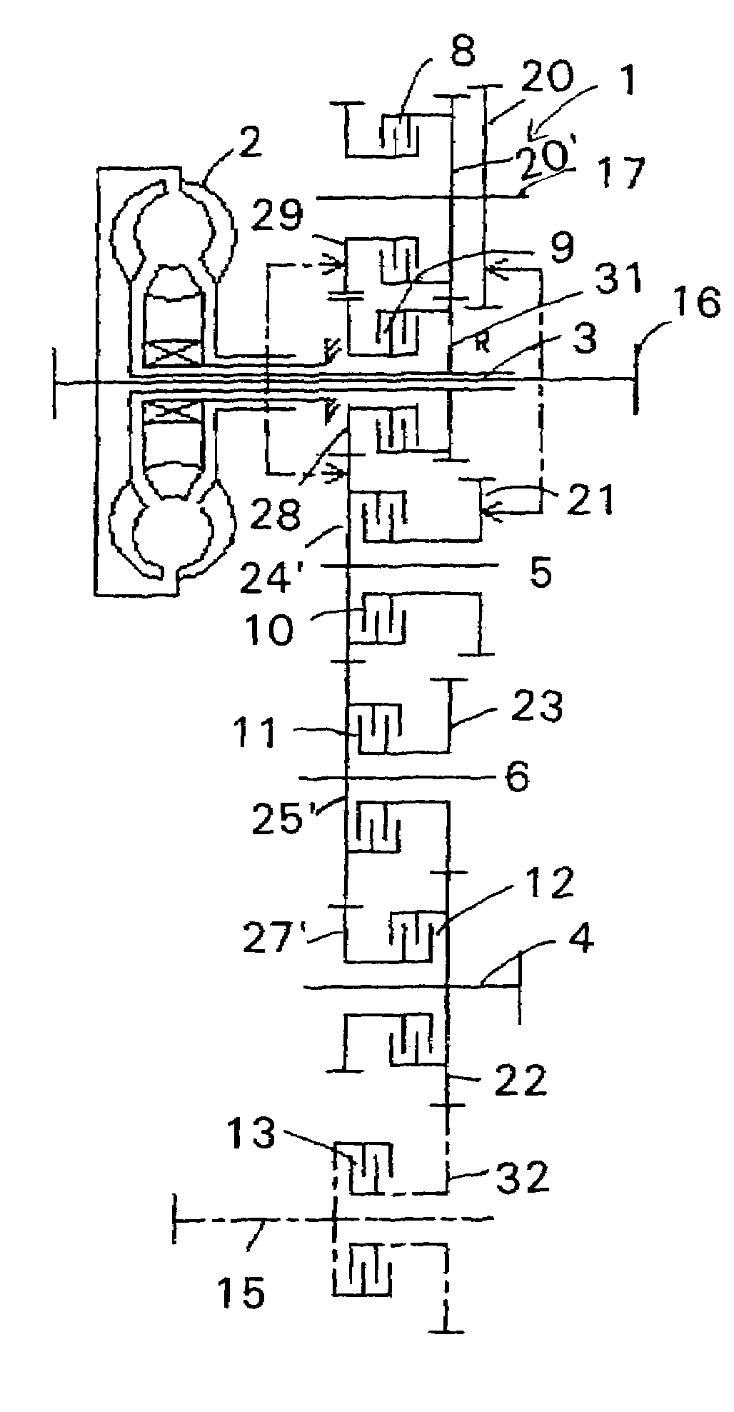
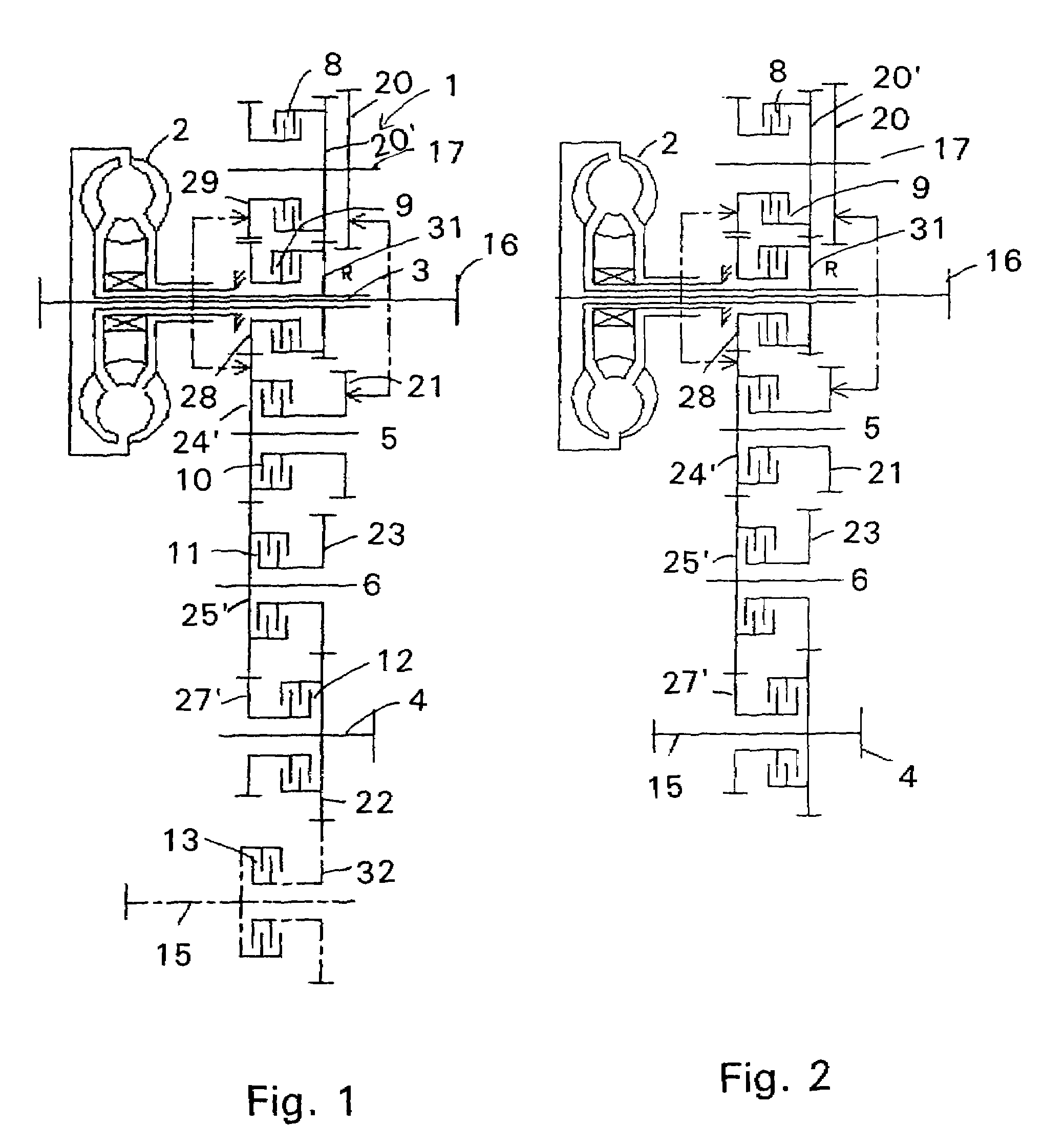
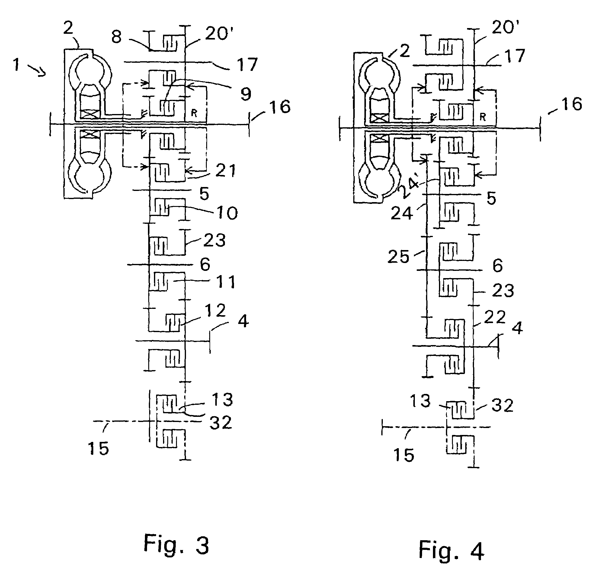
[0027]In FIG. 1, a read-adjustable, multi-geared reverse gear transmission 1 is shown, which has six forward gears and three reverse gears, with a torque converter 2, a drive shaft 3, an output shaft 4 and several jack shafts 5, 6, 7, 17 with these idlers distributed on the shafts, fixed wheels and shift clutches 8, 9, 10, 11, 12, which form several reduction gear units for the gearshift and direction circuit. Here the shift clutches 8 and 10 will be inserted as forward clutches; the rear clutch is provided with reference symbol 9. Furthermore, according to the transmission proposed in this invention, a separate, insertable front wheel drive 15 is proposed over a shift clutch 13, which is to be connected to a fixed wheel 22 of output shaft 4 over an idler 32, whereby this diagram is suitable for installation in excavator loaders in particular.

[0028]As can be inferred from FIG. 1, an auxiliary drive is proposed, for example PTO 16, which is primarily connected to the drive shaft 3.

[0...


PUM


Abstract

A multi-geared high-low clutch for construction machines with a torque converter, a drive shaft, an output shaft and several jack shafts, with distributed idlers on the shafts, fixed wheels and shift clutches, which form several reduction gear units for the gearshift and direction circuit, containing four forward gears and two reverse gears, whereby output shaft is also used as a jack shaft for a gear, with which the corresponding jack shaft of forward gear unit and the corresponding jack shaft of another forward gear unit engage with drive shaft, where both jack shafts can be rotated in every desired angle position around drive shaft, whereby corresponding jack shafts of the gears, applied to drive shaft, are arranged one behind the other on a side of the drive shaft and whereby, that corresponding jack shafts of the gears, can currently be rotated around the next visibly arranged jack shaft.

Description

[0001]This application is a national stage completion of PCT / EP2004 / 006122 filed Jun. 7, 2004 which claims priority from German Application Serial No. 103 30 157.7 filed Jul. 4, 2003.FIELD OF THE INVENTION[0002]The present invention concerns a powershift gearbox for construction machines, especially for a tractor backhoe loader and a telescopic handler.BACKGROUND OF THE INVENTION[0003]Such gear systems are usually implemented as reverse gear units and are fitted in many different construction machines, where the installation conditions, as a function of the type of motor vehicle, can fail differently. For example, the available fitting space, if it is extremely small, can fail. Furthermore, different axle bases between the transmission drive shaft and the transmission output shaft can occur; besides, depending on a type of motor vehicle, a certain axle placement between the entrance shaft and the output shaft of the gear system is necessary.[0004]An excavator loader vehicle demands ...

Claims


Application Information

Patent Timeline
Patent Type & Authority Patents(United States)
IPC IPC(8): F16H3/08F16H3/085F16H3/093F16H47/06
CPCF16H3/093F16H47/06F16H2003/0935Y10T74/19233F16H2200/0086Y10T74/19149Y10T74/19074F16H2200/0043A61H5/00
Inventor REGENSCHEIT, NORMAN
Owner ZF FRIEDRICHSHAFEN AG
Why Eureka
Try Eureka