Controller and control method for internal combustion engine

A technology for control devices and internal combustion engines, applied in internal combustion engine testing, engine control, internal combustion piston engines, etc., can solve problems such as unrecorded misfire detection, and achieve the effect of simple calculation and high-precision misfire detection

Active Publication Date: 2019-06-18
MITSUBISHI ELECTRIC CORP
View PDF7 Cites 8 Cited by
  • Summary
  • Abstract
  • Description
  • Claims
  • Application Information

AI Technical Summary

Problems solved by technology

In addition, [0119] of the same document states that it can be configured to use this technology to per...

Method used


Image

  • Controller and control method for internal combustion engine
  • Controller and control method for internal combustion engine
  • Controller and control method for internal combustion engine

Examples


Embodiment approach 1

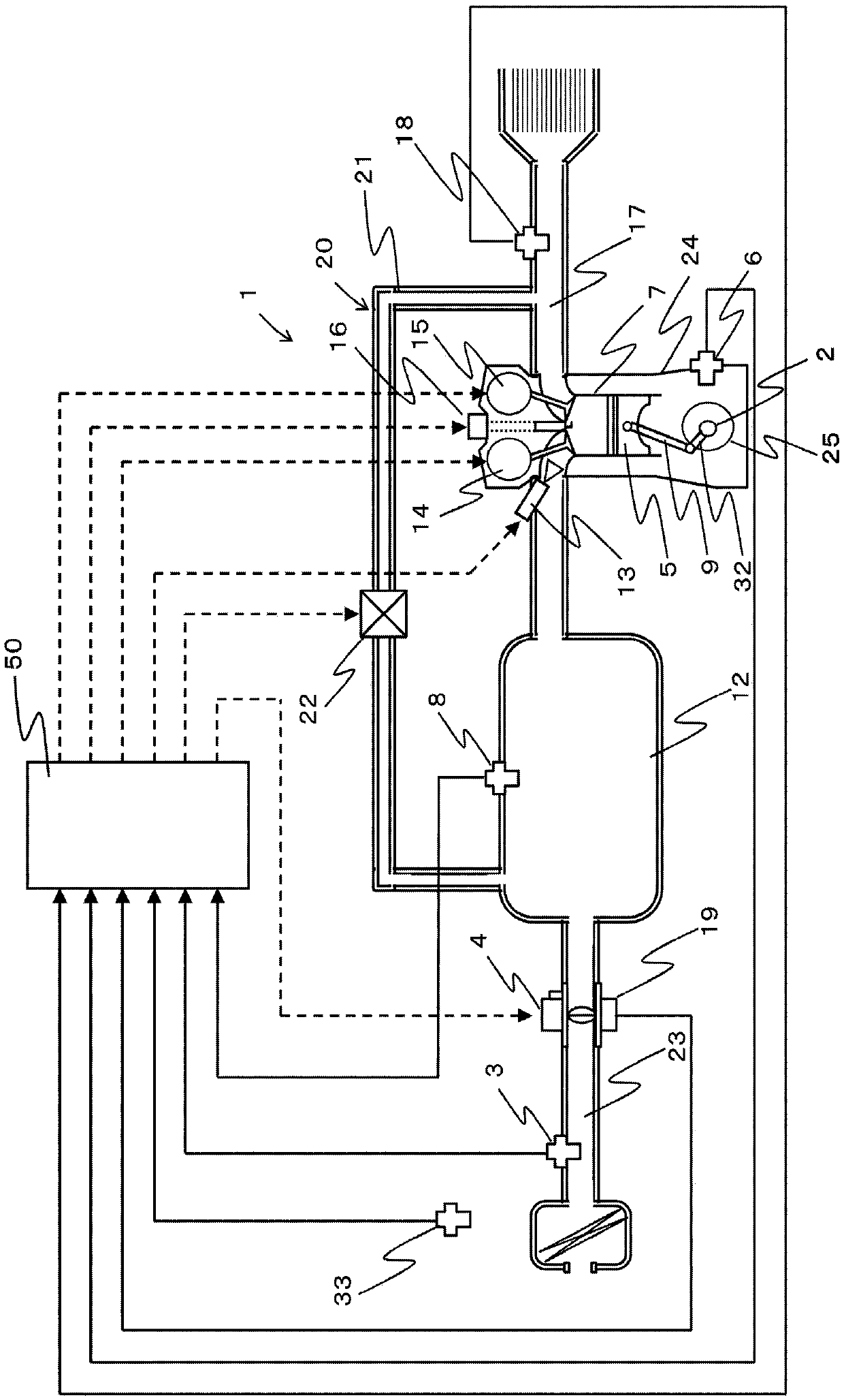
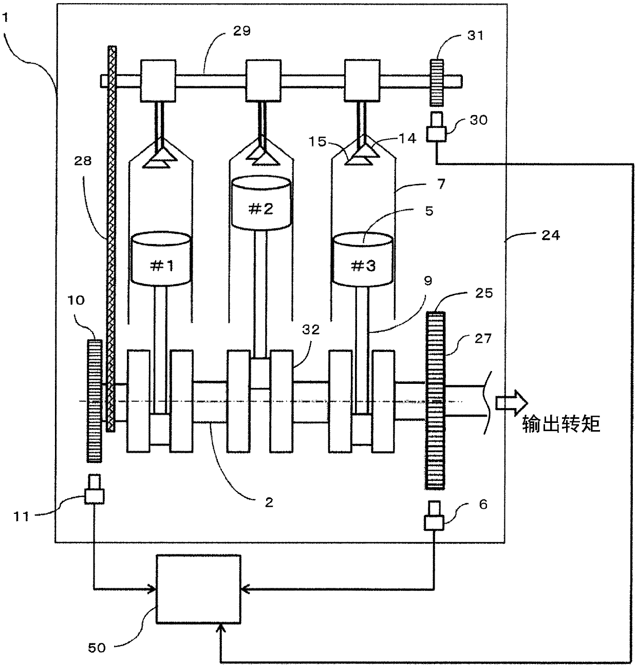
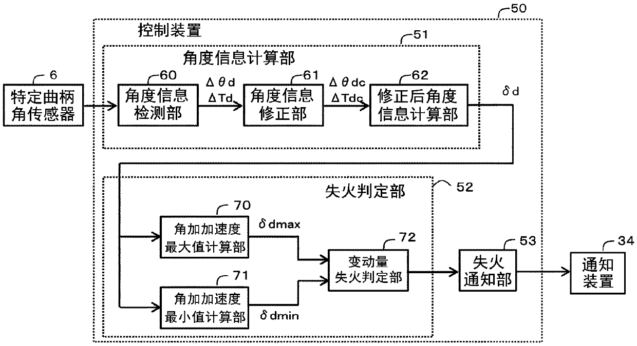
[0032] A control device 50 for an internal combustion engine (hereinafter simply referred to as the control device 50 ) according to Embodiment 1 will be described with reference to the drawings. figure 1 and figure 2 is a schematic configuration diagram of the internal combustion engine 1 and the control device 50 according to the present embodiment, image 3 It is a block diagram of the control device 50 according to this embodiment. The internal combustion engine 1 and the control device 50 are mounted on a vehicle, and the internal combustion engine 1 becomes a driving force source of the vehicle (wheels).

[0033] 1-1. Structure of internal combustion engine 1

[0034] First, the structure of the internal combustion engine 1 will be described. Such as figure 1 As shown, the internal combustion engine 1 includes a cylinder 7 that combusts a mixture of air and fuel. The internal combustion engine 1 includes an intake passage 23 that supplies air to the cylinders 7 and...


PUM


Abstract

To provide a controller and a control method for an internal combustion engine capable of detecting misfire with good accuracy by simple calculation, even when a vibration in a period of about severalstrokes occurs in the crankshaft. A controller 50 and a control method for an internal combustion engine detects crank angle [theta d] based on an output signal of the specific crank angle sensor 6,and calculates a crank angle speed [omega d], a crank angle acceleration [alpha d], and a crank angle jerk [delta d] which is a time change rate of the crank angle acceleration [alpha d]; calculates afluctuation amount [delta delta d] of the crank angle jerk [delta d] in a determination period which is set corresponding to a one combustion stroke based on the crank angle jerk [delta d]; and determines a presence/absence of misfire in the one combustion stroke based on the fluctuation amount [delta delta d] of the crank angle jerk.

Description

technical field [0001] The present invention relates to a control device and a control method for an internal combustion engine comprising a plurality of detected parts provided at a plurality of predetermined crank angles on a rotating member integrally rotating with a crankshaft, and a plurality of detected parts fixed to a non-rotating member and A specific crank angle sensor that detects the detected portion. Background technique [0002] Regarding the above-mentioned control device, for example, a technique described in Patent Document 1 below is known. In the technique of Patent Document 1, the crank angular velocity, the crank angular acceleration, and the crank angular jerk are calculated based on the output signal of the crank angle sensor, the error in the crank angle interval is corrected based on the crank angular jerk, and the crank angular velocity is corrected based on the corrected crank angular velocity. , crank angular acceleration to estimate the pressure...

Claims


Application Information

Patent Timeline
IPC IPC(8): F02B77/08
CPCF02D41/0097F02D41/1498F02D2200/101F02D2200/1012F02D41/22F02D2200/1015Y02T10/40B60W10/06F02D35/024F02D41/0047G01M15/11
Inventor 叶狩秀树
Owner MITSUBISHI ELECTRIC CORP
Why Eureka
Try Eureka