Tray piston swing pressure fluid feeding machine driven by crank-link mechanism

A technology of crank connecting rod mechanism and fluid machine, which is applied in the direction of swing piston type machinery, machine/engine, swing piston type pump, etc., can solve the problem of not finding

Inactive Publication Date: 2015-09-30
天津市石化通用机械研究所有限公司
View PDF12 Cites 8 Cited by
  • Summary
  • Abstract
  • Description
  • Claims
  • Application Information

AI Technical Summary

Problems solved by technology

[0004] In the existing public information, we have not found any similar information about the pallet piston swinging pressure-feeding fluid machine driven by the crank-link mechanism

Method used


Image

  • Tray piston swing pressure fluid feeding machine driven by crank-link mechanism
  • Tray piston swing pressure fluid feeding machine driven by crank-link mechanism
  • Tray piston swing pressure fluid feeding machine driven by crank-link mechanism

Examples


Embodiment 1

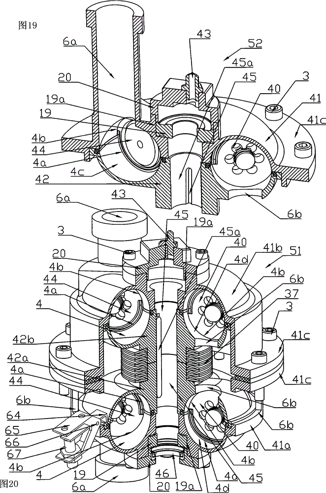
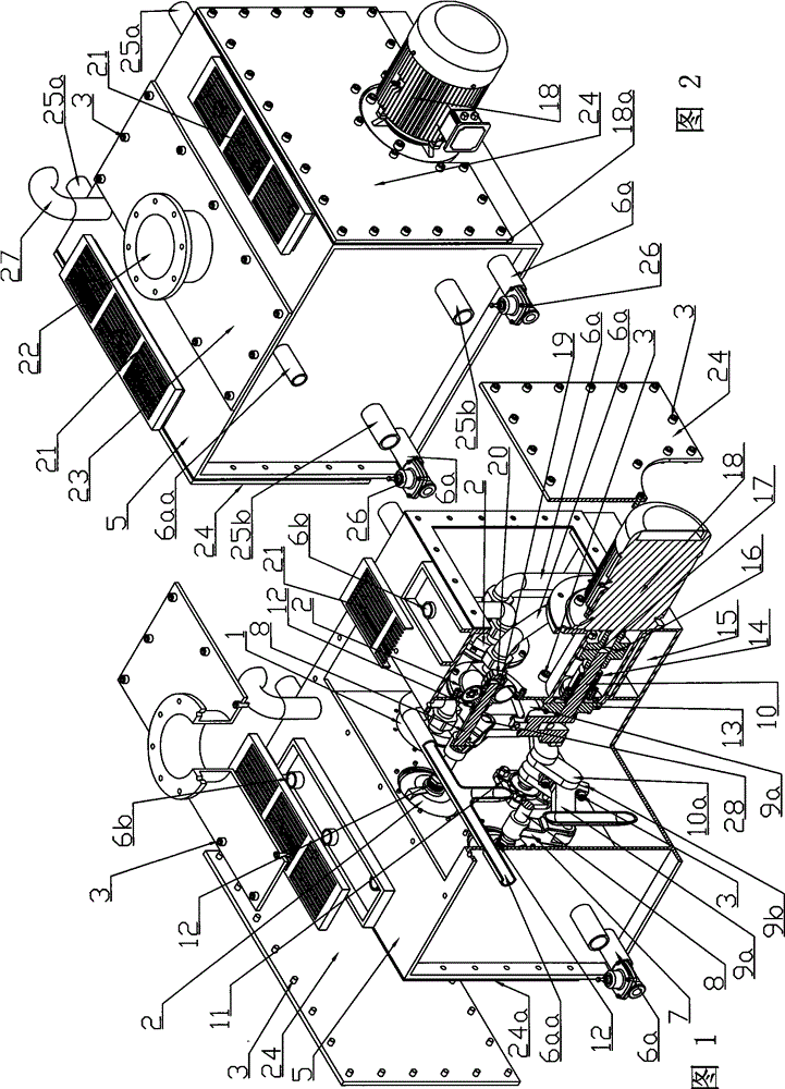
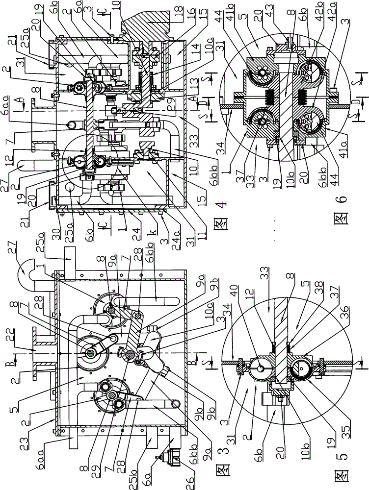
[0066] A pallet piston rocking press-feeding fluid machine driven by a crank-link mechanism, including a support shell 5, several pallet piston rocking actuators, a fluid inlet and outlet channel system, a cooling system, and a driving force generating system; the fluid inlet and outlet channel system includes Fluid passages, nozzles and valves, the fluid passages communicate with the working chamber 4c; the cooling system is a mechanism for forced cooling and / or natural heat dissipation of the components of the pressurized fluid machine; the pallet piston swing actuator includes 1 or 2 Fixed rocking tray group, piston piece, connecting mechanism, power entry and exit bonding structure, lubrication system and sealing structure; The pallet piston swing actuator A of the single solid rocking pallet group, the basic prototype of the device is the general embodiment 6 in the application numbers CN201410058100.X and 210420073755.X of "Pallet Piston Swing Drive Machine with Mechanica...

Embodiment 2

[0085] The difference between this embodiment 2 and embodiment 1 is in the following points, and all the other are basically the same as embodiment 1:

[0086] 1. In this embodiment 2, there are two types of pallet piston swing actuators, one of which is a pallet piston swing actuator B with a single solid rock pallet group using a fixed rock pallet group. The basic prototype of this device is " The overall embodiment 5 in the application numbers CN201410058100.X and 210420073755.X of the mechanically driven piston acting on the fluid load of the tray piston type swing driver; the second is the pair of clamp split swing tray piston type swing using two solid rocking tray groups Executing device B, the basic prototype of which is the general embodiment 5 in the application number CN201410092640.X and 201420114474.4 of "Piston Swing Drive Machine for Wafer Swing Tray Acting on Fluid with Mechanically Driven Piston";

[0087] 2. The crank-connecting rod transmission group is a cr...


PUM


Abstract

A tray piston type rocking fluid pressure-feeder driven by a crank connecting rod mechanism comprises a support housing (5), a plurality of tray piston type rocking execution devices (2), a fluid inlet and outlet passage system, a cooling system, and a driving force generation system. The fluid inlet and outlet passage system comprises a fluid passage (6, 6a, 6b), a pipe orifice and a valve. The fluid passage (6, 6a, 6b) is in communication with a working chamber (4c). The cooling system is a mechanism for forced cooling and/or natural heat dissipation of components of the fluid pressure-feeder. The support housing (5) is provided with n (n≥1) tray piston type rocking execution devices (2), rotating centerlines of rocking trays (36) of the n tray piston type rocking execution devices (2) are distributed on the same circumferential diameter around the rotating center of a driving crankshaft (10), and the rotating centerlines of the rocking trays (36) are perpendicular to a plane of a support wallboard (34). A system for mechanically driving pistons to act on a fluid load comprises a prime motor and a crank rocker mechanism. The reciprocating rocking range of an angular travel of rocking piston plates (40) is approximately 0 to 150 degrees, and the fluid pressure-feeder is applied to driving the pistons to pressure-feed a fluid for pumping work; and the pressure-fed fluid is gas or liquid.

Description

technical field [0001] The invention relates to a pallet-piston oscillating pressure-feeding fluid machine driven by a crank-connecting rod mechanism. The reciprocating swing range of the oscillating piston piece angular stroke is about 0-150°, which is suitable for driving the piston to pressure-feed fluid for pumping work; the pressure-feeding fluid The fluid that the motor drives the piston to press is gas or liquid. Background technique [0002] There are centrifugal pumps, plunger pumps and piston compressors in the existing disclosed pressure-feeding fluid machines. The stress intensity occurring in the dynamic process presents a higher-level peak-to-valley value change from small to large. As the highest stress-bearing parts, the connecting rod and the pin on the piston become the weak link that affects the life. In addition, due to the need to meet the large The strength requirements of the peak stress, many parts are basically made of metal materials, and the anti-...

Claims


Application Information

Patent Timeline
Patent Type & Authority Applications(China)
IPC IPC(8): F04C9/00F04C21/00F04C25/02
CPCF04C9/002
Inventor 张民良
Owner 天津市石化通用机械研究所有限公司
Why Eureka
Try Eureka