Kinematic coupling with textured contact surfaces

a technology of kinematic coupling and contact surface, which is applied in the direction of tray containers, transportation and packaging, packaging goods types, etc., can solve the problems of substrate or carrier damage, interfacial parts may sometimes be frictionally attached or “stick, hang up” or other problems, to achieve the effect of reducing frictional forces and less contact area

Active Publication Date: 2008-09-09
ENTEGRIS INC
View PDF18 Cites 21 Cited by
  • Summary
  • Abstract
  • Description
  • Claims
  • Application Information

AI Technical Summary

Benefits of technology

[0005]The present invention addresses the problem of sticking by providing a three-dimensional texture or pattern on contacting surfaces of equipment interface portions. The textured or patterned surface provides less contact area than a flat surface, thus reducing the frictional forces that cause sticking.

Problems solved by technology

If the carrier is not located at a tolerable height or orientation with respect to the processing equipment, the robotic manipulators may malfunction, causing delays in the assembly line as well as damage to the substrates or carrier.
A common problem encountered with the kinematic couplings is that the interface portions will sometimes frictionally adhere or “stick” to the contacting surfaces of the processing equipment.
If the sticking occurs before the carrier is stably seated on the mounting pins, the carrier may “hang up” and remain at an unacceptable height, or cause the carrier to list at an intolerable angle with respect to the robotic manipulators.
Also, as the robotic manipulators begin to handle the substrates, the carrier may suddenly slip off the stick point, causing the carrier to lurch downward and causing a risk of damaging contact between the robotic manipulators and the substrates.

Method used


Image

  • Kinematic coupling with textured contact surfaces
  • Kinematic coupling with textured contact surfaces
  • Kinematic coupling with textured contact surfaces

Examples


Embodiment Construction

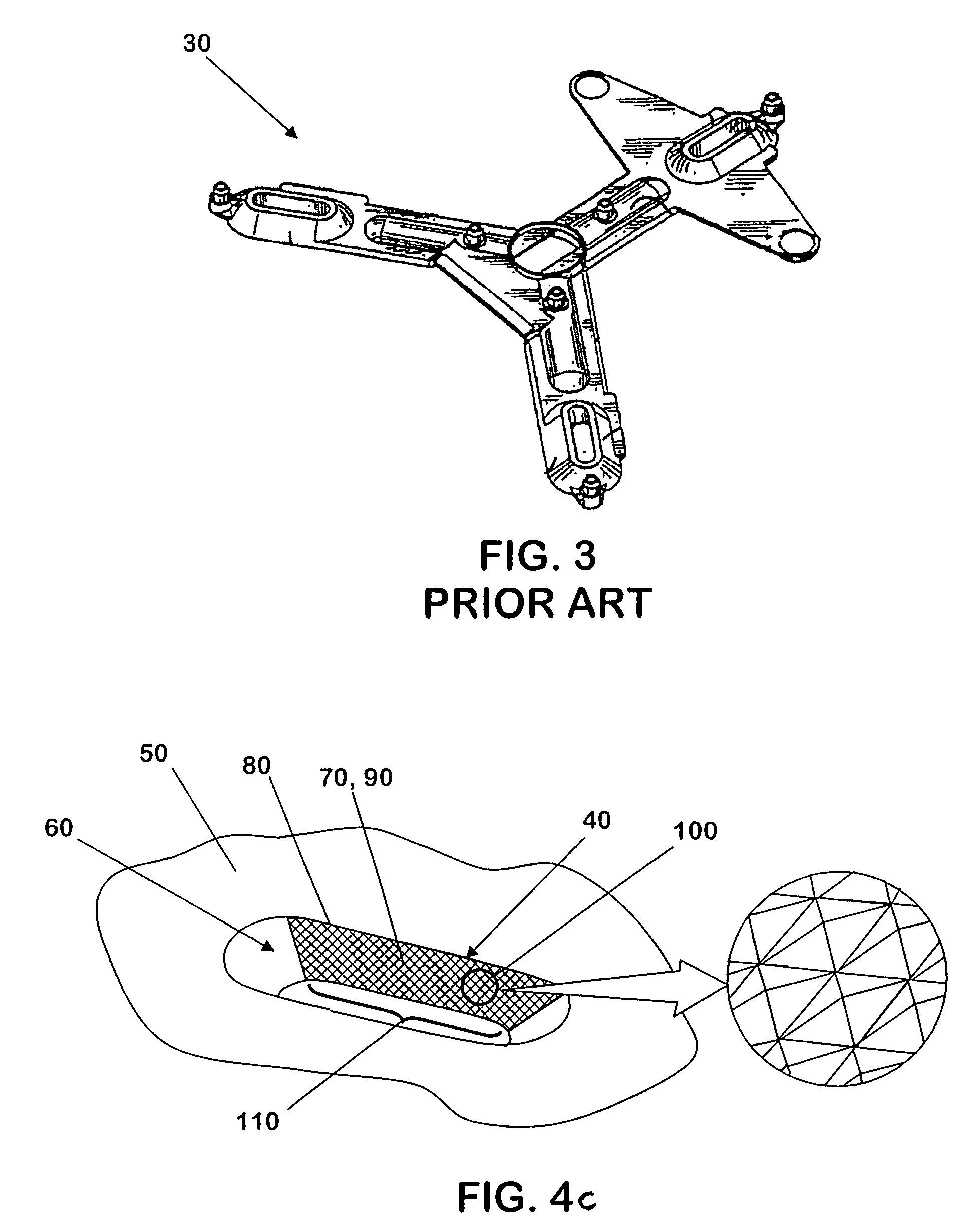
[0021]Referring to FIGS. 4a, 4b, and 4c, 300 mm wafer containers 31, 32 and an embodiment of an interface portion 40 of a kinematic coupling plate 50 according to the present invention are illustrated. The container of FIG. 4a has a container portion 33, a door 34, side handles 35, equipment interfaces configured as female kinematic coupling grooves 36, shown in phantom lines, side rails 37, a robotic flange 38, and key slots 39. The container seats on equipment 39.5 that has carrier interfaces, not shown in this view. Each of the equipment interfaces may have textured contact surfaces 39.6 as described in more detail below where the equipment interfaces may engage or contact the external equipment. Such equipment may be the keys for operating latching mechanisms, forks for engaging side rails, and robotic grasping members for grasping robotic flanges.

[0022]FIG. 4b illustrates a 300 mm wafer container with a kinematic coupling plate 50 affixed to the bottom side 51 of the container ...


PUM


Abstract

A substrate kinematic coupling or guide plate for a substrate carrier having textured or patterned surfaces at the points of contact to reduce frictional forces generated between automated processing equipment and the kinematic coupling. The textured surface reduces the contact area between the processing equipment and the contact portion of the kinematic coupling, thereby reducing the resultant frictional force. By reducing the frictional force, the substrate carrier more readily settles on the mounting pins of the processing equipment, thus avoiding intolerable height and angular deviations during automated access to the substrates. Textures include, but are not limited to, a knurl pattern, ridges running laterally along the contact portions, and ridges running longitudinally along the contact portions. The textures may be formed by a blow molding, injection molding or in an overmolding process, or by a machining or imprinting process.

Description

BACKGROUND OF THE INVENTION[0001]This invention relates to semiconductor processing equipment. More specifically, it relates to kinematic coupling of substrate carriers to processing equipment.[0002]Generally, substrate carriers, for example, 300 mm wafer containers, known as FOUPS (acronym for front opening unified pod) and FOSBS (acronym for front opening shipping container) include a downward facing equipment interface portion, such as a guide plate, that has a kinematic coupling, for properly orienting the carrier with respect to carrier interface portions provided by the processing equipment. The configuration of the equipment interface portions are typically dictated by industry standards promulgated by the Semiconductor Equipment and Materials International (SEMI). For 300 mm wafer containers the equipment interface located on the bottom of the containers are known as kinematic couplings. Other equipment interfaces may also exist on substrate carriers. Some substrate carriers...

Claims


Application Information

Patent Timeline
Patent Type & Authority Patents(United States)
IPC IPC(8): B65D85/86
CPCH01L21/67379Y10S414/14H01L21/67383
Inventor BURNS, JOHNFORBES, MARTIN L.FULLER, MATTHEW A.KING, JEFFERY J.SMITH, MARK V.
Owner ENTEGRIS INC
Why Eureka
Try Eureka