Joining assembly for fixing a tube at a holder

a technology for joining assemblies and holder plates, which is applied in the direction of braking systems, machine supports, braking components, etc., can solve the problems of relatively high weight of steel members, relatively complex operation, and relatively high cost, and achieves simple and cost-effective manufacturing and assembly.

Inactive Publication Date: 2008-09-09
BOLLHOFF VERBINDUNGSTECHNIK GMBH
View PDF31 Cites 30 Cited by
  • Summary
  • Abstract
  • Description
  • Claims
  • Application Information

AI Technical Summary

Benefits of technology

[0004]It is an object of the present invention to provide a joining assembly for fixing a tube at a holder, which may be made totally of plastic material and which allows for extremely simple and cost effective manufacture and assembly thereof.
[0006]Accordingly, all of the total joining assembly is made of plastic material so that corrosion problems are avoided. Furthermore, the use of plastic material allows substantially to reduce the weight of the joining assembly. The two sleeve members and the bracket may be readily manufactured by injection molding. Machining operations such as turning and milling are not required. Furthermore, dividing the sleeve into a pair of sleeve members avoids the requirement of axially inserting the tube into the sleeve; rather, the tube may be laterally inserted into one of the sleeve members before the two sleeve members are snappingly connected to each other. This manner of assembling the joining assembly is particularly suited for automatic operations. As a result processing in the assembly line is significantly simplified. Furthermore, the fact that the tube can be inserted into the sleeve by lateral movement provides for mounting flexibility so that the joining assembly can be adapted to varying dimensions and varying positions of the sleeve relative to the tube. Finally a sleeve “crimping” operation as in the prior art is not required.

Problems solved by technology

This joining assembly of the prior art suffers from the drawbacks that the steel sleeve is a complex and expensive part requiring turning and milling operations, that the surface protection of the involved members may be damaged by the “crimping” operation so as to cause corrosion problems, that the assembling operation which requires insertion of the brake fluid tube into the steel sleeve and a following “crimping” operation is relatively complex and expensive, and that the steel members are of relatively high weight.

Method used


Image

  • Joining assembly for fixing a tube at a holder
  • Joining assembly for fixing a tube at a holder
  • Joining assembly for fixing a tube at a holder

Examples


Embodiment Construction

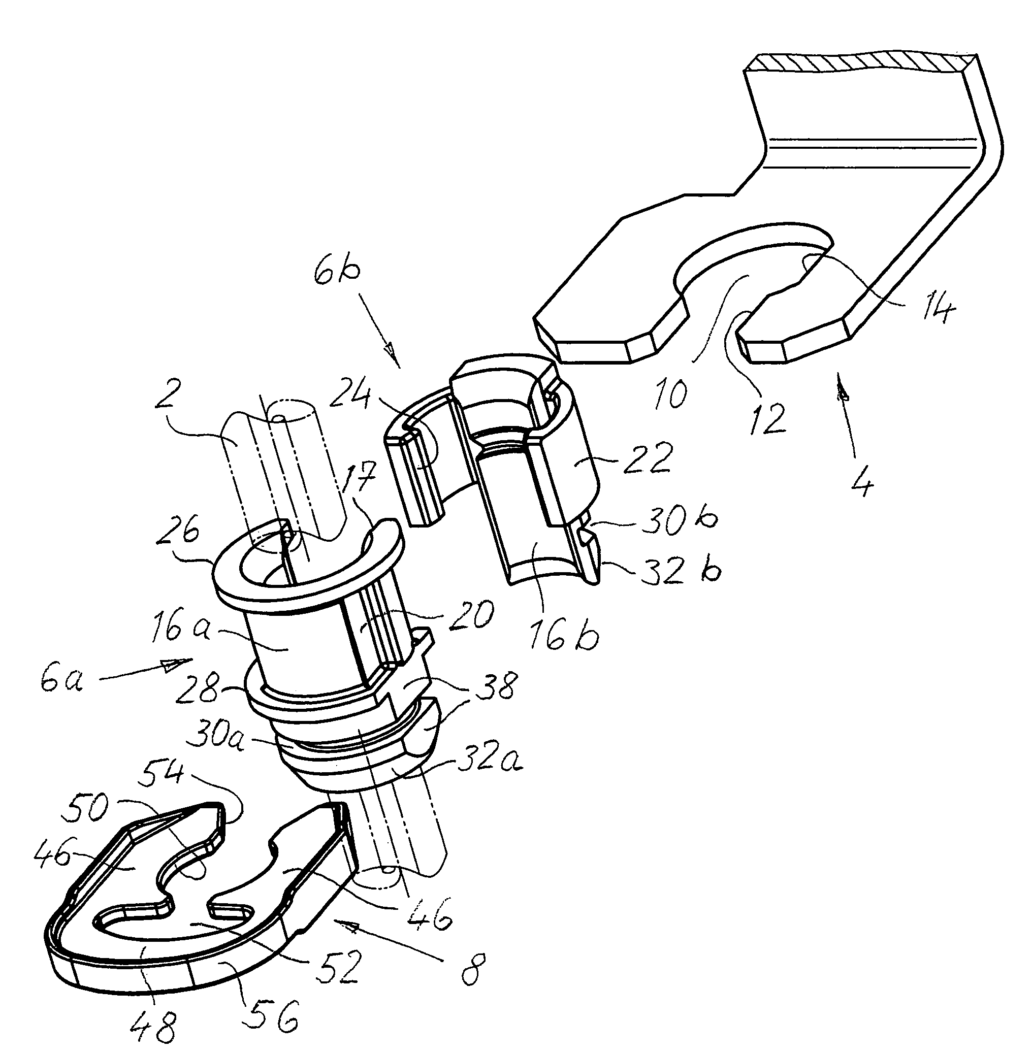
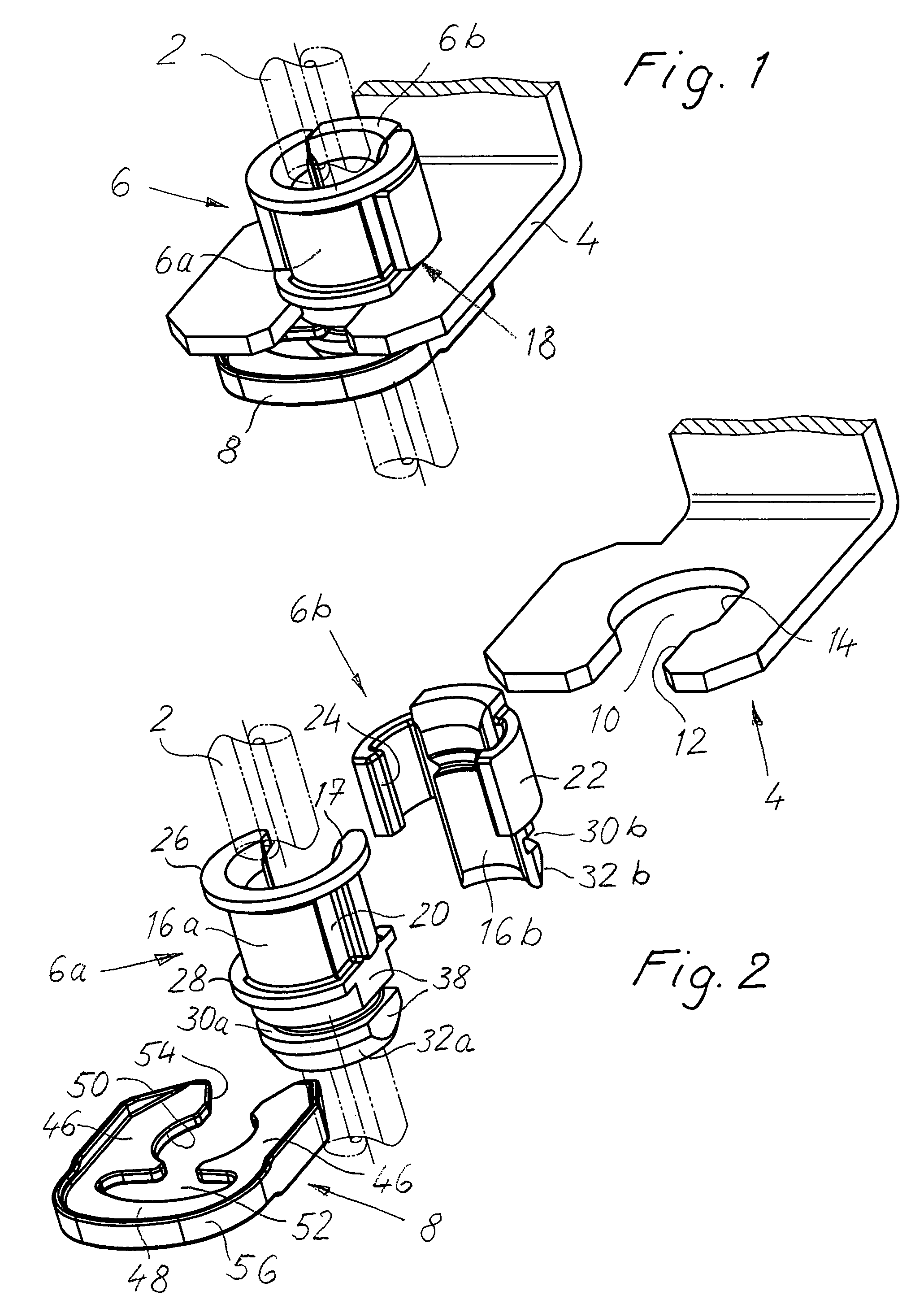
[0017]The joining assembly shown in FIGS. 1 and 2 is adapted to fix a flexible brake fluid tube or hose 2 (indicated by dash dotted lines) to a holder 4 which is mounted to a vehicle body (not shown) of a vehicle adjacent to a brake cylinder (not shown) of a front wheel so that the flexible tube or hose 2 will be deflected by steering movements of the front wheel. The joining assembly provides for tensional stress relief of the tube 2 which is held stationary, by the joining assembly, to the holder 4 both circumferentially as well as axially and radially as will be explained in more detail below.

[0018]The joining assembly comprises a sleeve 6 which consists of a pair of connectable sleeve members 6a, 6b, and a bracket or clamp 8. All of these members are made of plastic material. The sleeve 6 consisting of the two sleeve members 6a, 6b is fixed at the holder 4 by the bracket 8 as will be explained in more detail below.

[0019]The holder 4 is a plate shaped member having a circular hol...


PUM


Abstract

A joining assembly for fixing a flexible tube at a plate shaped holder. The joining assembly comprises first and second sleeve members made of plastic material and adapted to be joined by snap-lock means so as to form a closed sleeve clampingly receiving the flexible tube, and a bracket made of plastic material and adapted to engage the closed sleeve so as to fix it in a hole of the holder.

Description

BACKGROUND OF THE INVENTION[0001]The present invention relates to a joining assembly for fixing a tube at a holder, in particular for fixing a brake fluid tube at a holder fixedly mounted to a vehicle.[0002]Such brake fluid tube connectors are mounted for example at the vehicle body adjacent to a brake cylinder for a front wheel of a vehicle and are adapted in particular to provide tensional stress relief of the flexible brake fluid tube which extends to the brake cylinder and performs respective movements as a result of steering movements of the front wheel. In the prior art there has become known such a joining assembly which comprises a steel sleeve and a steel bracket or clamp which fix the brake fluid tube at a plate shaped holder of the vehicle body. For mounting the joining assembly to the vehicle body a portion of the brake fluid tube is inserted into the bore of the steel sleeve and thereafter is deformed in a folding area such that internal annular cutting edges of the sle...

Claims


Application Information

Patent Timeline
Patent Type & Authority Patents(United States)
IPC IPC(8): F16L5/00B60T17/04F16L3/10
CPCF16L3/10B60T17/046
Inventor SU.BETA.ENBACH, RAINER
Owner BOLLHOFF VERBINDUNGSTECHNIK GMBH
Why Eureka
Try Eureka