Sample-loading system and anti-collision device and anti-collision method thereof

a sample-loading system and anti-collision technology, applied in the field of sample-loading systems, can solve the problems of sample-loading system colliding with other equipment, damage to the sample-loading system, test errors, etc., and achieve the effect of preventing the sample-loading system from colliding with other objects

Active Publication Date: 2008-09-09
SHENZHEN MINDRAY BIO MEDICAL ELECTRONICS CO LTD
View PDF12 Cites 0 Cited by
  • Summary
  • Abstract
  • Description
  • Claims
  • Application Information

AI Technical Summary

Benefits of technology

[0009]An object of the present invention is to provide an anti-collision device used for a sample-loading system, and an anti-collision method, both of which use a low-cost design to effectively prevent the sample-loading system from colliding with other objects in the process of movement.
[0021]According to the present invention, whether a collision occurs during the movement of the sample-loading system is found out through location detection. Specifically, the rotating process of the sample-loading system is fractionalized into a number of phases, and the sample-loading system continuously and sequentially moves to an appointed location during the whole movement process. Every time the sample-loading system moves to the next location from the present location, the drive motor needs to rotate for certain steps designed by the system. Beginning from the present location, if the drive motor has rotated for the designed steps, while the sample-loading system doesn't arrive to the next location yet, it shows that the sample-loading system encounters collisions and the system whereupon stops working and gives an alarm. Thus, the personal safety is ensured and the apparatus is protected from being damaged. As compared with the prior art, the present invention achieves the following advantageous effect. 1) The mechanical structure is simple. The present invention only necessitates a code plate, a detecting optical coupler and corresponding circuits, either the code plate or the optical coupler fixed, the other movable along with the moving mechanism. Thereby, a relative movement exists between the code plate and the optical coupler, whereby the location detection is achievable using the optical coupler to detect the light penetrating gaps of the code plate. As seen from this, the size of the sample-loading system is not increased, which is helpful to miniaturize the sample-loading system. 2) The processing circuit is simple, which only demands the acquisition of the optical coupler signal. 3) The detecting process is easily achievable. 4) Acceleration and deceleration have no effect on the present invention which is associated with location only, so inaccurate judgments will not occur. 5) High detecting sensitivity is achieved.

Problems solved by technology

Also, a manipulative error maybe causes the sample-loading system to collide with other equipments.
Either of the above-mentioned collisions can result in damages to the sample-loading system and errors in the test result.
What is more serious is that the collision maybe causes injuries to the person.
Moreover, the provision of the sensors also enhances the cost of the product (i.e., the sample-loading system with the sensors).
Thus, the system has to be equipped with an accessorial signal-processing part, as a result of which its design is more complicated and inaccurate judgments tends to happen.
Similar to the acceleration detection, this solution also demands an accessorial signal-processing part, and the design thereof is rather complicated.

Method used


Image

  • Sample-loading system and anti-collision device and anti-collision method thereof
  • Sample-loading system and anti-collision device and anti-collision method thereof
  • Sample-loading system and anti-collision device and anti-collision method thereof

Examples


Embodiment Construction

[0027]Reference will now be made to the figures to describe the present invention in detail.

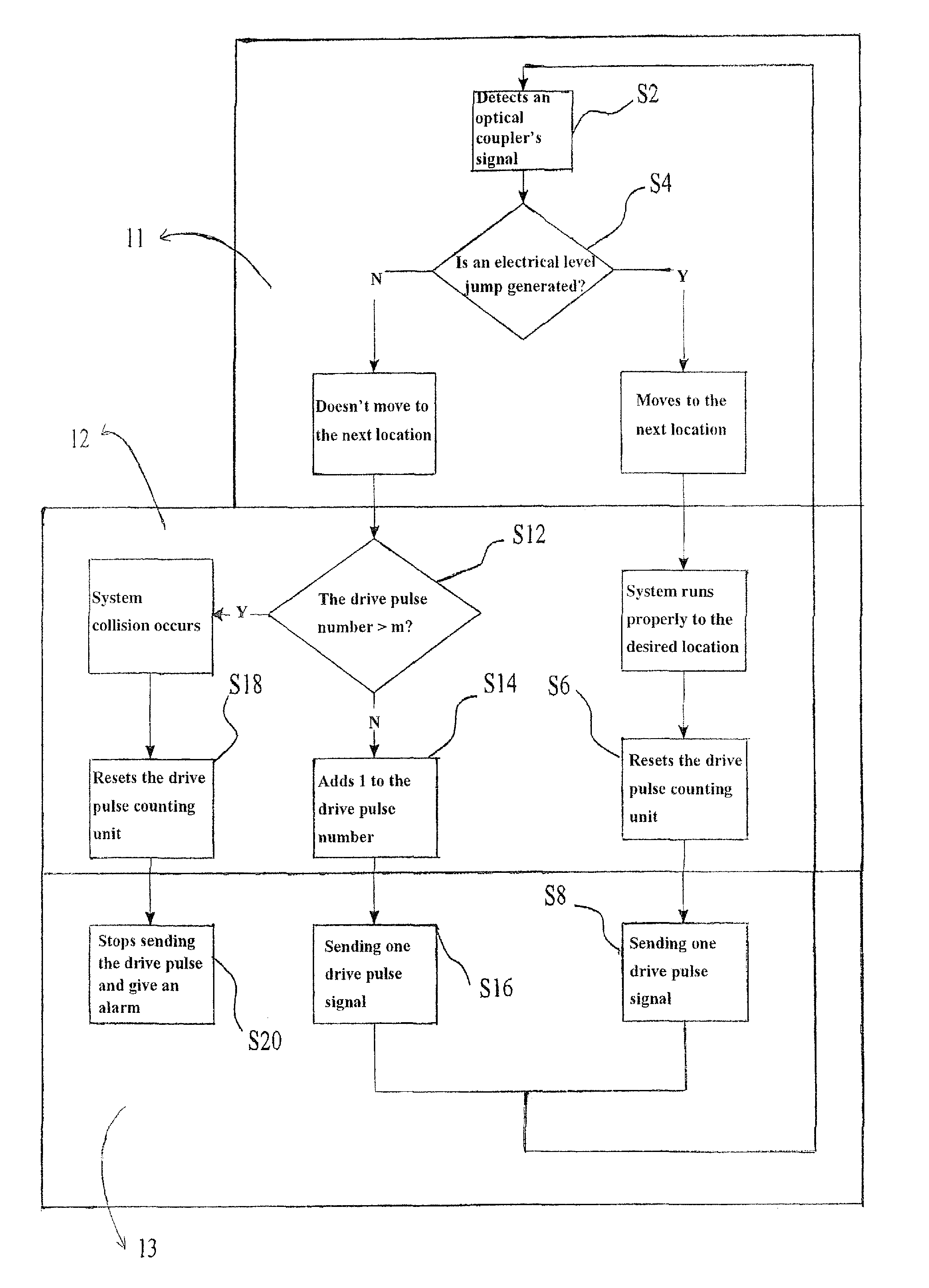
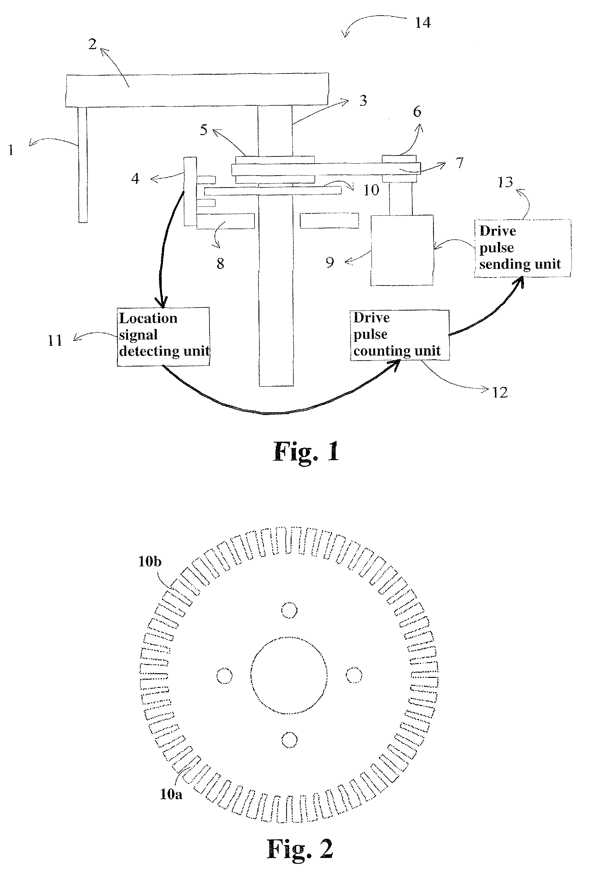
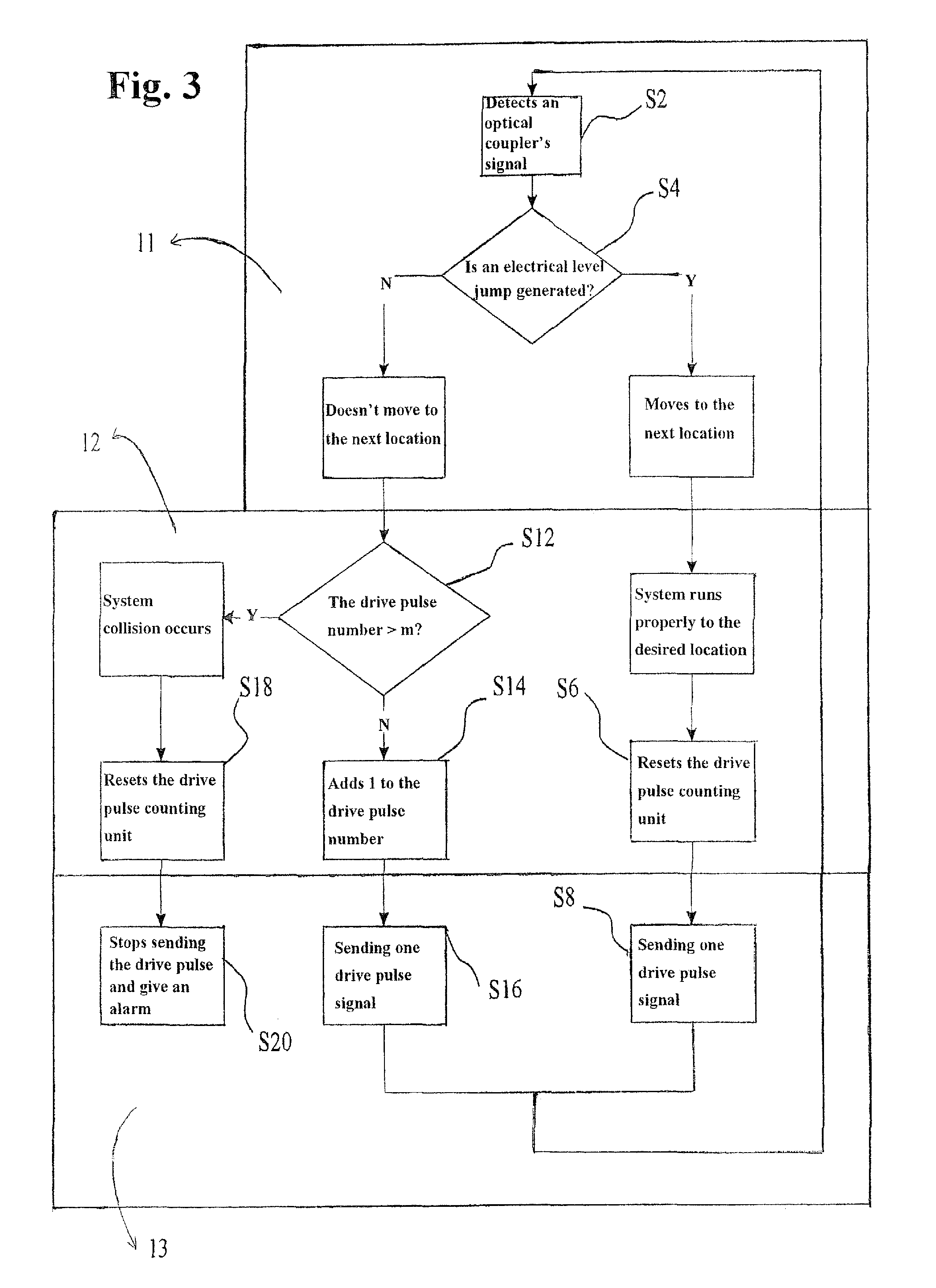
[0028]Referring to FIG. 1, a rotation-mode sample-loading system 14 in accordance with the first preferred embodiment of the present invention is shown. In this embodiment, the moving mechanism is a rotation axle 3. A drive motor 9 connects to a small belt wheel 6 and drives it to rotate. The small belt wheel 6 connects to a large belt wheel 5 via a synchronous belt 7 and transfers a rotation movement thereto. The large belt wheel 5 drives the rotation axle 3 and a code plate 10 to synchronously move (i.e., to rotate). A probe 1 connects to a rocking arm 2 and is rotated to an appointed position by the rocking arm 2 driven by the rotation axle 3 connected thereto. The code plate 10 is a circular disk and defines a number of equidistant gaps 10a at the periphery thereof, which gaps can be strip-shaped or dentate holes, or alternatively circular holes as shown in FIG. 2. The code plate 10 fixed...


PUM


Abstract

Some embodiments of the present invention provide an anti-collision device used for a sample-loading system. This device may include a code plate, an optical coupler, a location signal-detecting unit, a drive pulse counting unit and a drive pulse-sending unit. The optical coupler detects the code plate during the relative movement between the optical coupler and the code plate and outputs detection signals. The location signal detecting unit determines whether to output location signals to the drive pulse counting unit. The drive pulse counting unit judges whether collisions occur to the sample-loading system. Some embodiments of the present invention provide an anti-collision method and a sample-loading system comprising the anti-collision device.

Description

RELATED APPLICATIONS[0001]This application claims priority to Chinese Patent Application 200610062502.2, filed on Sep. 7, 2006, the contents of which are hereby incorporated by reference herein in its entirety.BACKGROUND OF THE INVENTION[0002]1. Field of the Invention[0003]The present invention generally relates to sample-loading systems applied to the fields such as medical treatment, chemical industry etc. and, more particularly, to an anti-collision device and an anti-collision method thereof.[0004]2. Discussion of the Related Art[0005]Sample-loading systems are often used in medical treatment and chemical industry. Nowadays, the commonly adopted sample-loading systems are capable of automatically taking samples and loading the samples. In the process of movement (e.g., rotary movement or linear movement), the sample-loading system maybe collides with a person that is replacing a sample or a reagent, or collides with other objects. Also, a manipulative error maybe causes the samp...

Claims


Application Information

Patent Timeline
Patent Type & Authority Patents(United States)
IPC IPC(8): G05B1/06G05B11/01G05B19/29
CPCG01N35/00G05B19/048G05B2219/42288G05B2219/37622G05B2219/37175
Inventor WENG, YANWENHU, JIANKUNZHU, XINGCAI
Owner SHENZHEN MINDRAY BIO MEDICAL ELECTRONICS CO LTD
Why Eureka
Try Eureka