Method and system for contrast enhancement of digital video

a technology of contrast enhancement and digital video, applied in the field of digital video contrast enhancement, can solve the problems of video contrast enhancement, over-contrast pictures, slow processing, etc., and achieve the effects of enhancing the overall picture contrast of digital video signals, improving subjective quality, and enhancing picture contras

Active Publication Date: 2008-09-09
STMICROELECTRONICS ASIA PACIFIC PTE
View PDF18 Cites 48 Cited by
  • Summary
  • Abstract
  • Description
  • Claims
  • Application Information

AI Technical Summary

Benefits of technology

[0011]The disclosed embodiments of the invention enhance the overall picture contrast of a digital video signal so that it gives a better subjective quality without introducing artifacts that degrade the picture quality and enhance the picture contrast without introducing flickering.

Problems solved by technology

The need for video contrast enhancement may arise due to the picture contrast distortions caused by transmission limitations or the limitations of video capturing devices or media.
It is known that mapping functions generated by the CDF of the picture histogram tend to over-enhance or over-correct the contrast, resulting in over-contrast pictures.
Mapping functions that are generated by picture pre-processing, for example performing quantization or filtering, may involve complex processing, which can be slow to process.
As for the selection of predetermined types of mapping curves using only the average brightness of blocks in each picture, the technique may be too simplistic and lack the accuracy required for determining the most appropriate mapping function to be used.
Methods that divide a picture into blocks and select mapping functions for each block according to its difference with the average block luminance level can be highly complex and flickering could also result.
For any existing system that has selectable or switchable mapping functions in place but lack an automatic mapping functions selection mechanism, the existing techniques described above either require too complex design changes to such a system or the mapping function selection method is too simplistic and lacks accuracy.

Method used


Image

  • Method and system for contrast enhancement of digital video
  • Method and system for contrast enhancement of digital video
  • Method and system for contrast enhancement of digital video

Examples


Embodiment Construction

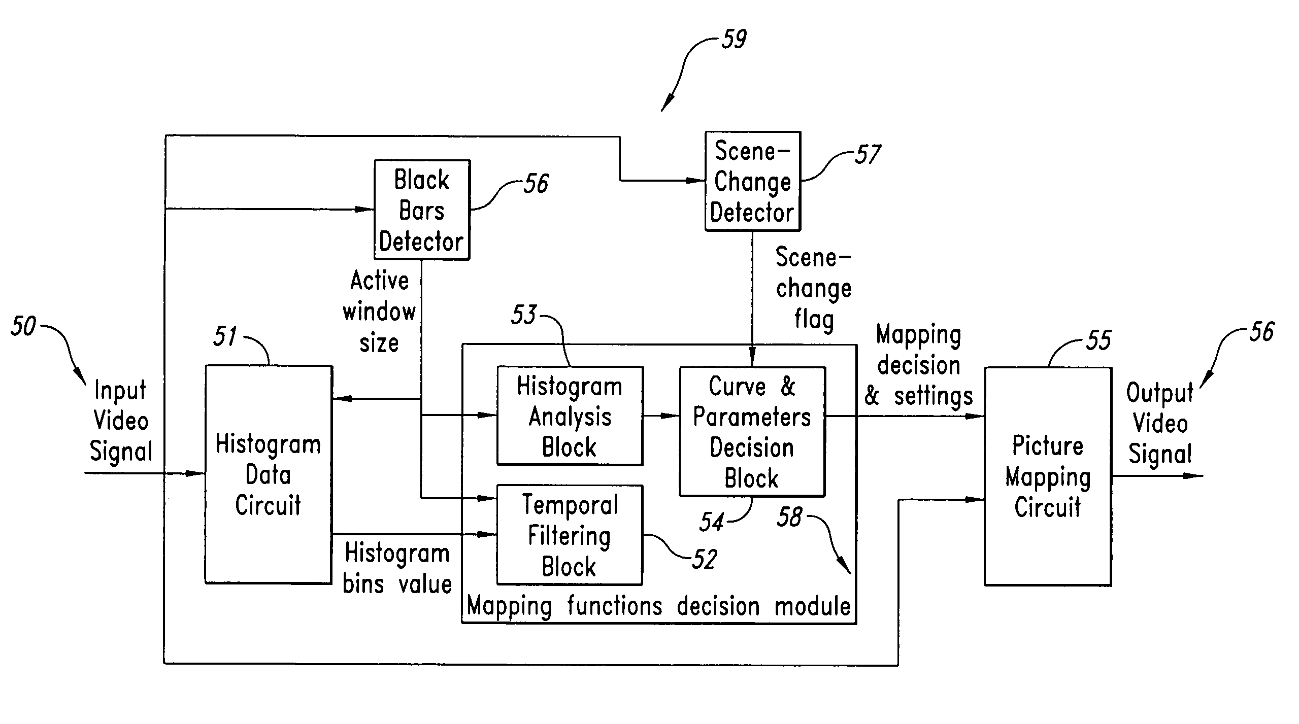
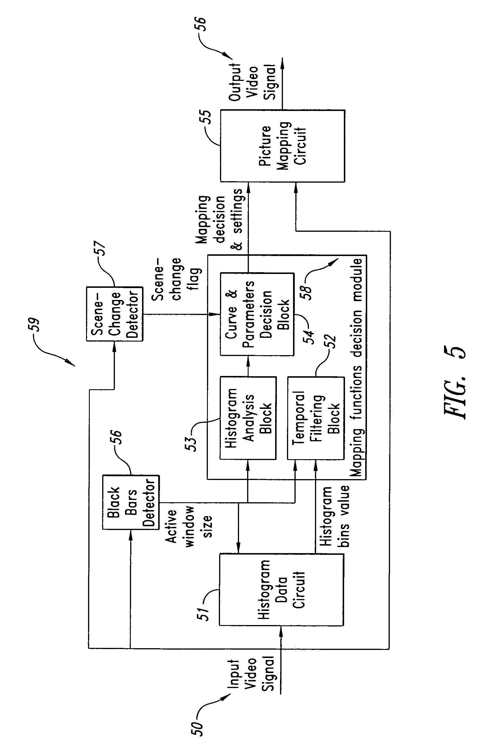
[0041]FIG. 5 is a block diagram of a contrast enhancement device showing the main components thereof and indicated as Contrast Enhancer 59. Preferably, the Contrast Enhancer 59 has a Histogram Data Circuit 51, Black Bars Detector Module 56, Scene Change Detector 57, a Mapping Functions Decision Module 58 and a Picture Mapping Circuit 55. The Histogram Data Circuit 51 receives a digital input video signal 50 and generates a histogram corresponding to each picture or frame extracted from the digital input video signal 50. The generated histogram represents the varying degrees of luminance of the pixels in each picture. The generated histogram may be of higher complexity for greater accuracy, for example representing the 8-bit grey level output of the current picture using a 256-band histogram, or alternatively be of lower complexity allowing faster processing, for example using a 16-band histogram similar to the one shown in FIG. 6.

[0042]As shown in FIG. 6, each band 60 (or bin) in th...


PUM


Abstract

A method for enhancing the contrast of video pictures that includes the steps of receiving an input video signal; extracting a picture from said input video signal; determining an active window for said picture; calculating a histogram for luminance values of pixels in said active window of said picture; determining characteristics of said histogram; selecting one suitable mapping function from a plurality of mapping functions based on the determined characteristics of said histogram; and mapping the luminance value of each pixel in said picture in accordance with said selected mapping function.

Description

BACKGROUND OF THE INVENTION[0001]1. Field of the Invention[0002]The present invention relates to a method and system for enhancing the overall picture contrast of digital video signals by using an automatically configurable mapping function that is automatically selected from a predetermined set of mapping functions based on set criteria.[0003]2. Description of the Related Art[0004]The need for video contrast enhancement may arise due to the picture contrast distortions caused by transmission limitations or the limitations of video capturing devices or media. Examples of video signals requiring contrast enhancement are video pictures that are too dark, too bright, too low in contrast or are over contrast.[0005]Mapping functions are normally used to map the original luminance values for each respective pixel in a picture or video frame into new respective values. FIGS. 1 to 4 illustrate different examples of such mapping functions. In FIGS. 1 to 4, the horizontal axis represents the ...

Claims


Application Information

Patent Timeline
Patent Type & Authority Patents(United States)
IPC IPC(8): G06K9/00G06K9/40H04N5/52G06T5/00G06T5/40
CPCG06T5/009G06T5/40G06T2207/10016
Inventor GOH, KWONG HUANG
Owner STMICROELECTRONICS ASIA PACIFIC PTE
Why Eureka
Try Eureka