Anti-slip control method for a drive system in a motor vehicle

a technology of a drive system and a control method, which is applied in the direction of brake systems, instruments, tractors, etc., can solve the problems of reducing the total wheel torque, and achieve the effect of reducing the need for complex coordination of the wheel torque control

Inactive Publication Date: 2008-09-09
BAYERISCHE MOTOREN WERKE AG
View PDF11 Cites 8 Cited by
  • Summary
  • Abstract
  • Description
  • Claims
  • Application Information

AI Technical Summary

Benefits of technology

[0007]The invention suggests an integrated approach in which the accelerator pedal is used as a power control element and, by way of its variable interpretation, to power output to the wheels is controlled such that occurring wheel slip is first reduced and is avoided during the subsequent regulating, in order to minimize the necessity of a complex coordination of a wheel torque control by several individual components.

Problems solved by technology

Furthermore, transmission control devices are known which themselves react to the spin tendency of the driving wheels, in that, by changing the effective ratio, they reduce the total wheel torque until the determined wheel slip has been reduced.

Method used


Image

  • Anti-slip control method for a drive system in a motor vehicle
  • Anti-slip control method for a drive system in a motor vehicle

Examples


Embodiment Construction

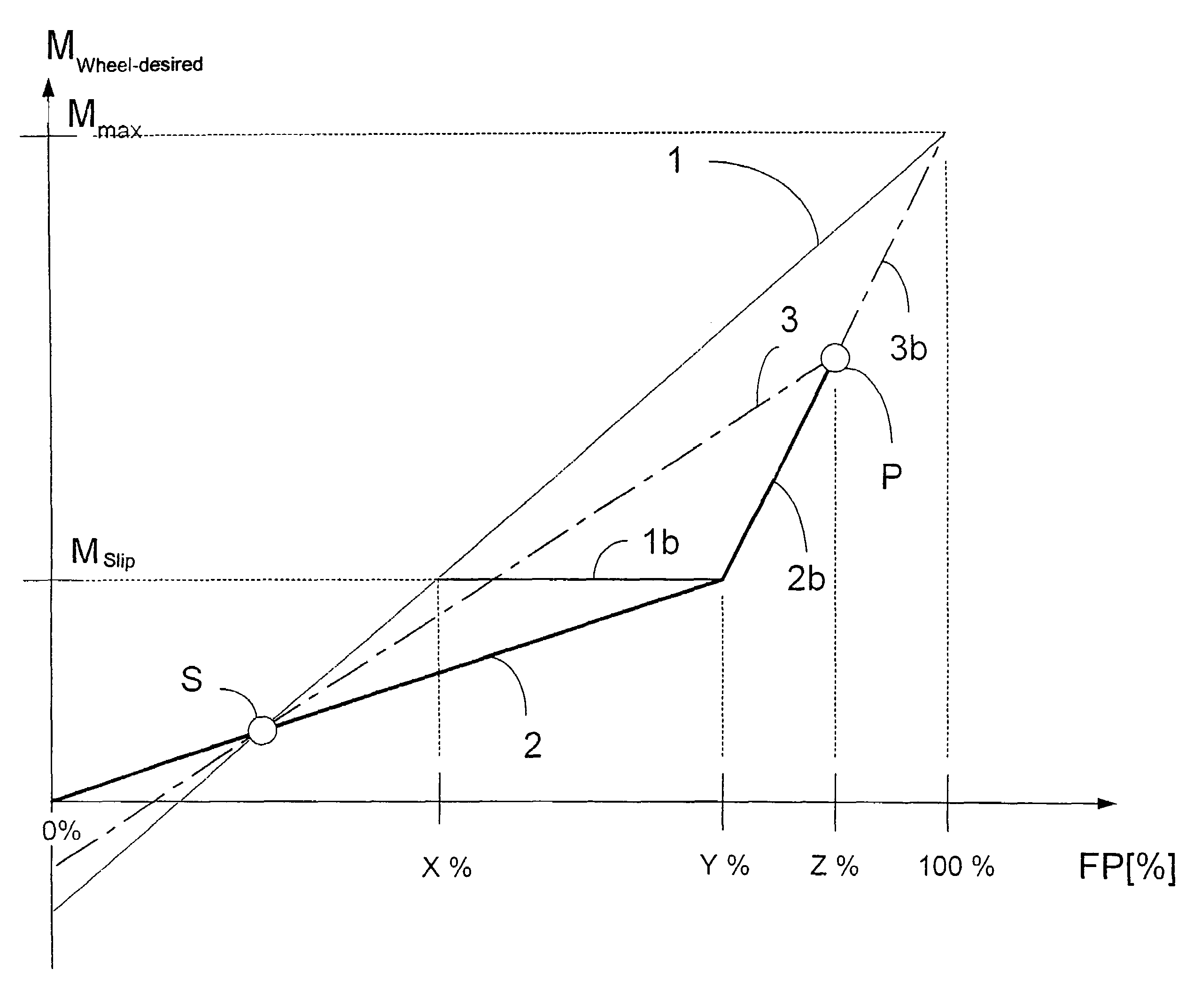
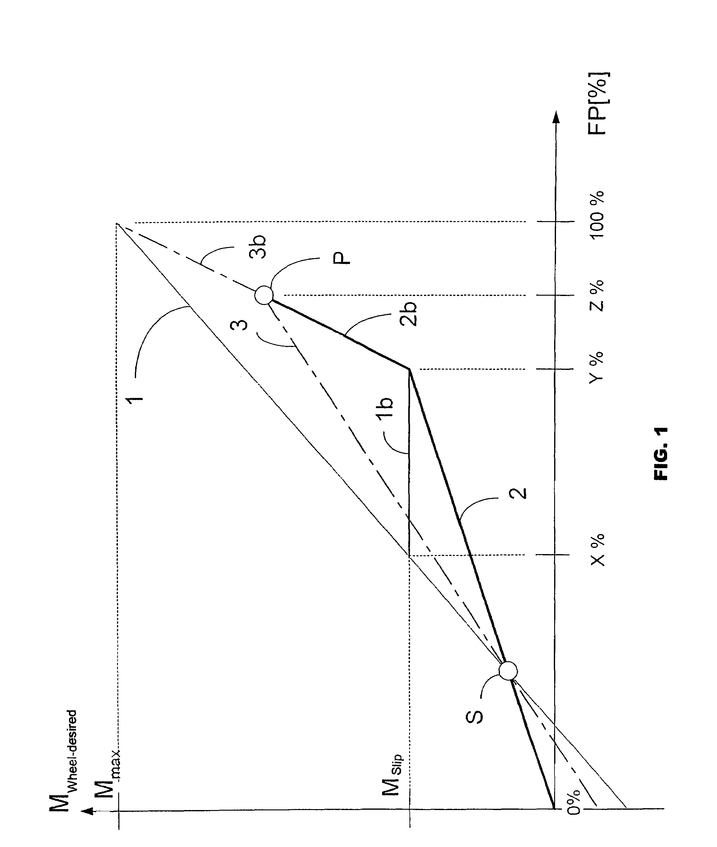
[0013]The method according to the invention, which is carried out by an electronic control device, will be explained in detail by means of characteristic curves illustrated in the drawing.

[0014]The electronic control device, for example, an internal-combustion engine control device and / or an automatic transmission control device present anyhow and not shown, receives the accelerator pedal position FP as an input signal as well as information concerning the presence of wheel slip. Corresponding to stored characteristic curves or characteristic diagrams, the control device determines a wheel torque Mwheel-desired desired by the driver as a function of the accelerator pedal position FP and, as required, as a function of additional operating parameters not explained here in detail.

[0015]For the method according to the invention, only the dependence on the accelerator pedal position PD will be explained when determining the desired wheel torque Mwheel-desired or the power demand.

[0016]Wh...


PUM


Abstract

A method for controlling a drive system in a motor vehicle having at least one electronic control device, which detects the accelerator pedal position as an input signal and therefrom, corresponding to a basic characteristic curve, determines a wheel torque desired by the driver, the control device receives information concerning the presence of wheel slip as another input signal and, when wheel slip is present, stores a limit torque. For an accelerator pedal position which is greater than the accelerator pedal position at which the wheel slip has occurred, the basic characteristic curve is changed in that the desired wheel torque is limited to the limit torque.

Description

[0001]This application is a Continuation of PCT / EP2005 / 010553, filed Sep. 30, 2005, and claims the priority of DE 10 2004 050 994.8, filed Oct. 20, 2004, the disclosures of which are expressly incorporated by reference herein.BACKGROUND AND SUMMARY OF THE INVENTION[0002]The invention relates to a method of controlling a drive system in a motor vehicle having an electronic control device which determines a desired wheel torque from an accelerator pedal position.[0003]Such a method is known, for example, from German Patent Document 196 37 210 A1. In the case of this known method, on the one hand, the wheel torque demanded by way of the accelerator pedal and, on the other hand, a conglomeration of various operating parameters are processed with one another in a central unit in a manner not shown in detail for controlling the drive system.[0004]It is an object of the invention to improve a method of controlling a drive system in a motor vehicle with a view to optimizing comfort.[0005]Th...

Claims


Application Information

Patent Timeline
Patent Type & Authority Patents(United States)
IPC IPC(8): B60T7/12
CPCB60K28/16B60W2520/26B60W2710/105B60W2540/10B60W2520/28
Inventor FUCHS, EMANUELSCHUMACHER, HUBERT
Owner BAYERISCHE MOTOREN WERKE AG
Why Eureka
Try Eureka