Rotary type fluid machine

a fluid machine and rotary technology, applied in the direction of positive displacement liquid engine, piston pump, liquid fuel engine, etc., can solve the problems of insufficient supply and discharge of working medium, restricted axial movement of valve main body,

Inactive Publication Date: 2005-10-06
HONDA MOTOR CO LTD
View PDF6 Cites 6 Cited by
  • Summary
  • Abstract
  • Description
  • Claims
  • Application Information

AI Technical Summary

Benefits of technology

[0005] In order to accomplish this object, in accordance with a first aspect of the present invention, there is proposed a rotary fluid machine that includes a casing, a rotor rotatably supported in the casing, an operating part provided in the rotor, and a rotary valve that is provided between the casing and the rotor and controls the intake and discharge of a working medium to and from the operating part via sliding surfaces that are perpendicular to the axis of the rotor, the rotary fluid machine further including a working medium supply pipe provided separately from the rotary valve, the working medium supply pipe being positioned on the axis of the rotor and supplying the working medium to the rotary valve, and sealing means disposed between the working medium supply pipe and the rotary valve, the sealing means having the function of preventing movement of the

Problems solved by technology

However, in this conventional rotary fluid machine, since the working medium supply pipe is fixed to the valve main body, axial movement of the valve main body is restricted by the working medium supply pipe, or vibration of the working medium supply p

Method used


Image

  • Rotary type fluid machine
  • Rotary type fluid machine
  • Rotary type fluid machine

Examples


Embodiment Construction

[0015] An embodiment of the present invention is explained below with reference to the attached drawings.

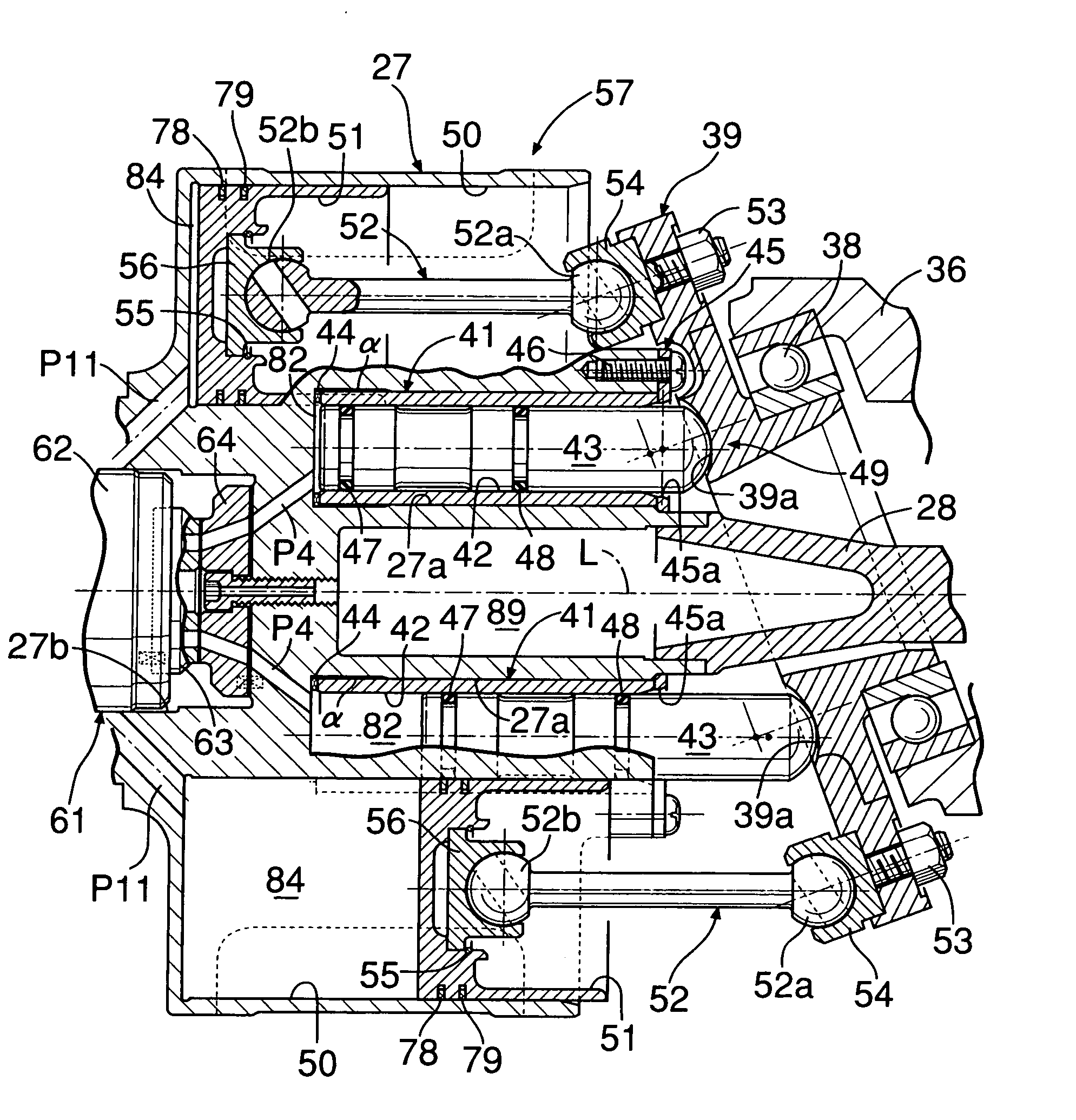
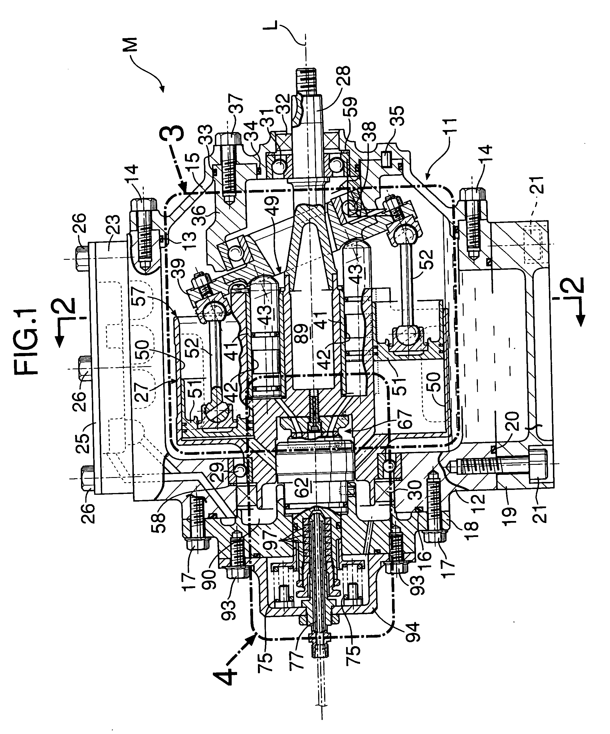
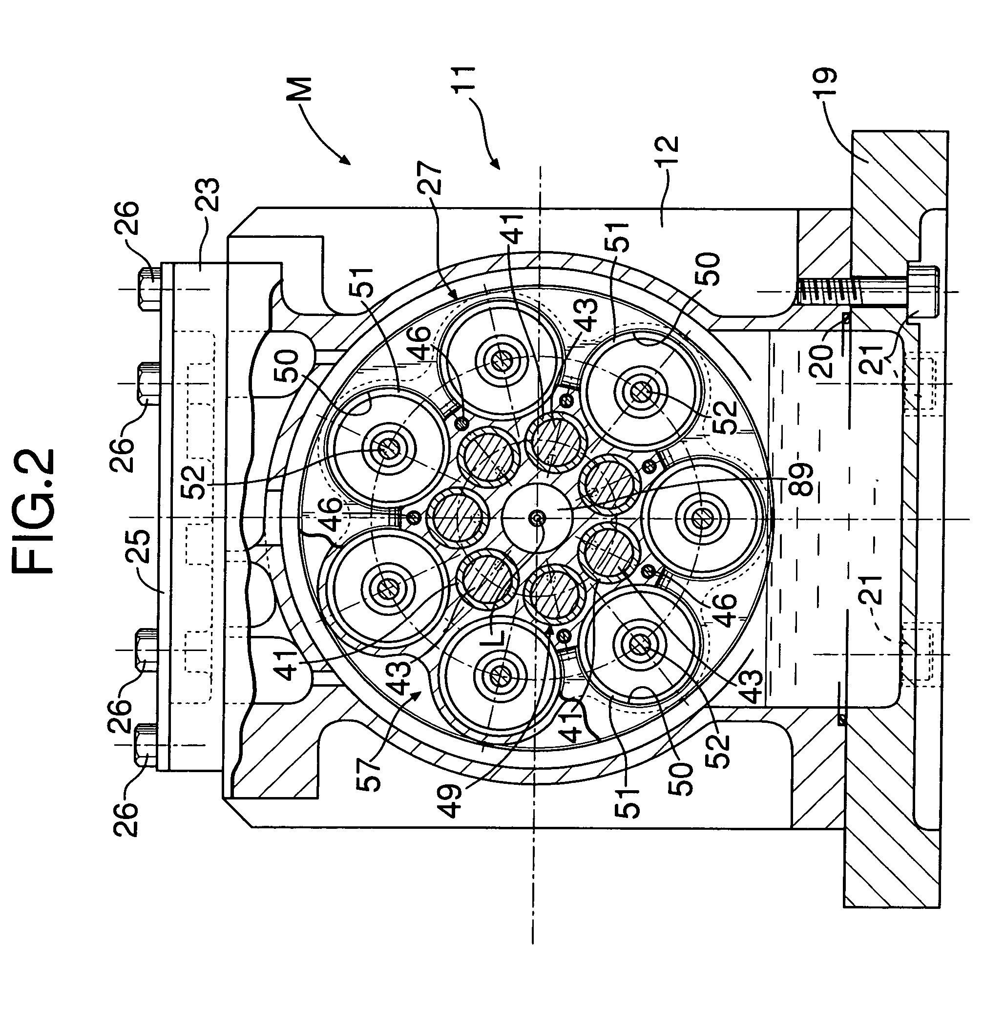
[0016] As shown in FIG. 1 to FIG. 3, a rotary fluid machine of the present invention is, for example, an expander M used in a Rankine cycle system, and the thermal energy and the pressure energy of high-temperature, high-pressure steam as a working medium are converted into mechanical energy and output. A casing 11 of the expander M is formed from a casing main body 12, a front cover 15 fitted via a seal 13 in a front opening of the casing main body 12 and joined thereto via a plurality of bolts 14, and a rear cover 18 fitted via a seal 16 in a rear opening of the casing main body 12 and joined thereto via a plurality of bolts 17. An oil pan 19 abuts against a lower opening of the casing main body 12 via a seal 20 and is joined thereto via a plurality of bolts 21. Furthermore, a breather chamber dividing wall 23 is superimposed on an upper face of the casing main body 12, a brea...


PUM


Abstract

A rotary fluid machine is provided that includes a rotary valve (61) for controlling the intake and discharge of a working medium to and from an operating part (49, 57) formed from an axial piston cylinder group, a steam supply pipe (77) that is disposed on an axis (L) of a rotor (27) and supplies steam to the rotary valve (61), the steam supply pipe (77) being provided separately from a rotary valve main body (62), and gland packing sealing means (97) disposed between the steam supply pipe (77) and the rotary valve main body (62). Since the sealing means (97), which is flexible, has the function of preventing movement in the direction of the axis (L) of the steam supply pipe (77) from being transmitted to the rotary valve (61), it is possible to ensure the intimacy of contact of sliding surfaces (68) of the rotary valve (61) while minimizing the leakage of steam past the outer periphery of the steam supply pipe (77) by means of the sealing means (97), thereby enabling the steam to be supplied and discharged reliably.

Description

FIELD OF THE INVENTION [0001] The present invention relates to a rotary fluid machine that includes a casing, a rotor rotatably supported in the casing, an operating part provided in the rotor, and a rotary valve that is provided between the casing and the rotor and controls the intake and discharge of a working medium to and from the operating part via sliding surfaces that are perpendicular to the axis of the rotor. BACKGROUND ART [0002] The rotary valve of this type of rotary fluid machine generally includes a valve main body fixed to the casing so as to be positioned on the axis of the rotor, and controls the supply and discharge of the working medium via sliding surfaces of the fixed valve main body and the rotating rotor. Supply of the working medium to the rotary valve is carried out via a working medium supply pipe fixed to the valve main body so as to be disposed on the axis of the rotor, and the valve main body is resiliently biased toward the rotor so that the working med...

Claims


Application Information

Patent Timeline
IPC IPC(8): F01B3/02F04B1/20F04B1/22F04B27/08
CPCF01B3/02F04B1/205F04B1/22F04B27/0808F04B27/0843
Inventor HONMA, KENSUKENAKINO, HIROYUKI
Owner HONDA MOTOR CO LTD
Why Eureka
Try Eureka