
Window blind

a technology for windows and blinds, applied in door/window protective devices, building components, construction, etc., can solve the problems of no privacy at all, unpleasant for people's eyes, and heating up the interior of a hous

Inactive Publication Date: 2008-09-16
LAI TONY
View PDF5 Cites 29 Cited by
  • Summary
  • Abstract
  • Description
  • Claims
  • Application Information

AI Technical Summary

Benefits of technology

"The present invention provides a lift cord operation system for a window blind with an alternation hanging device to provide diversified shading effects. The system includes a top support, bottom support, slats, folding unit, and supplement blind enhancement. The supplement blind enhancement includes enhancing blades and a control system to alternately block or enhance sunlight passing through the window. The technical effects of the invention include evenly bearing tension on each hanging net, maintaining a fixed distance between neighboring hanging nets, and preventing the lift cord from homing back to define an undesirable shading effect."

Problems solved by technology

However, the traditional window blind has several drawbacks.
When the slats are upwardly received, sunlight would directly enter the window thus not only heating up the interior of a house but also unpleasing to people's eye.
Furthermore, there is no privacy at all because the interior of the house is easily viewed from outside.
Therefore, user unwillingly has to make a tough decision between privacy and light from predetermined gap.
Unfortunately, this lift cord disposed on the side end of the window would impose a cumbersome problem for the user.
It is highly unlikely for a user to balancedly lift up the whole alternation hanging device.
Even a pulley device could be provided at such openings, there is no guarantee that the hanging net would be passing in and out from the head rail in a smooth manner.
In a long run, such an unbalanced tension would cause the lift rod close to the adjacent hanging net worn off or broken.
Unfortunately, once the lift lock is utilized to lock the lifted alternation hanging device, the lift lock would withstand overall weight of the alternation hanging device, the floating gear wheel would be released a little bit for biasing against the lift cord.
This homing release would be undesirable even intolerable to most users.
This is due to the fact that the homing movement of the floating gear wheel would lower the predetermined set of the slats supported by the alternation hanging device away from the remaining slats thus ruining the shading effect.

Method used


Image

  • Window blind
  • Window blind
  • Window blind

Examples


Embodiment Construction

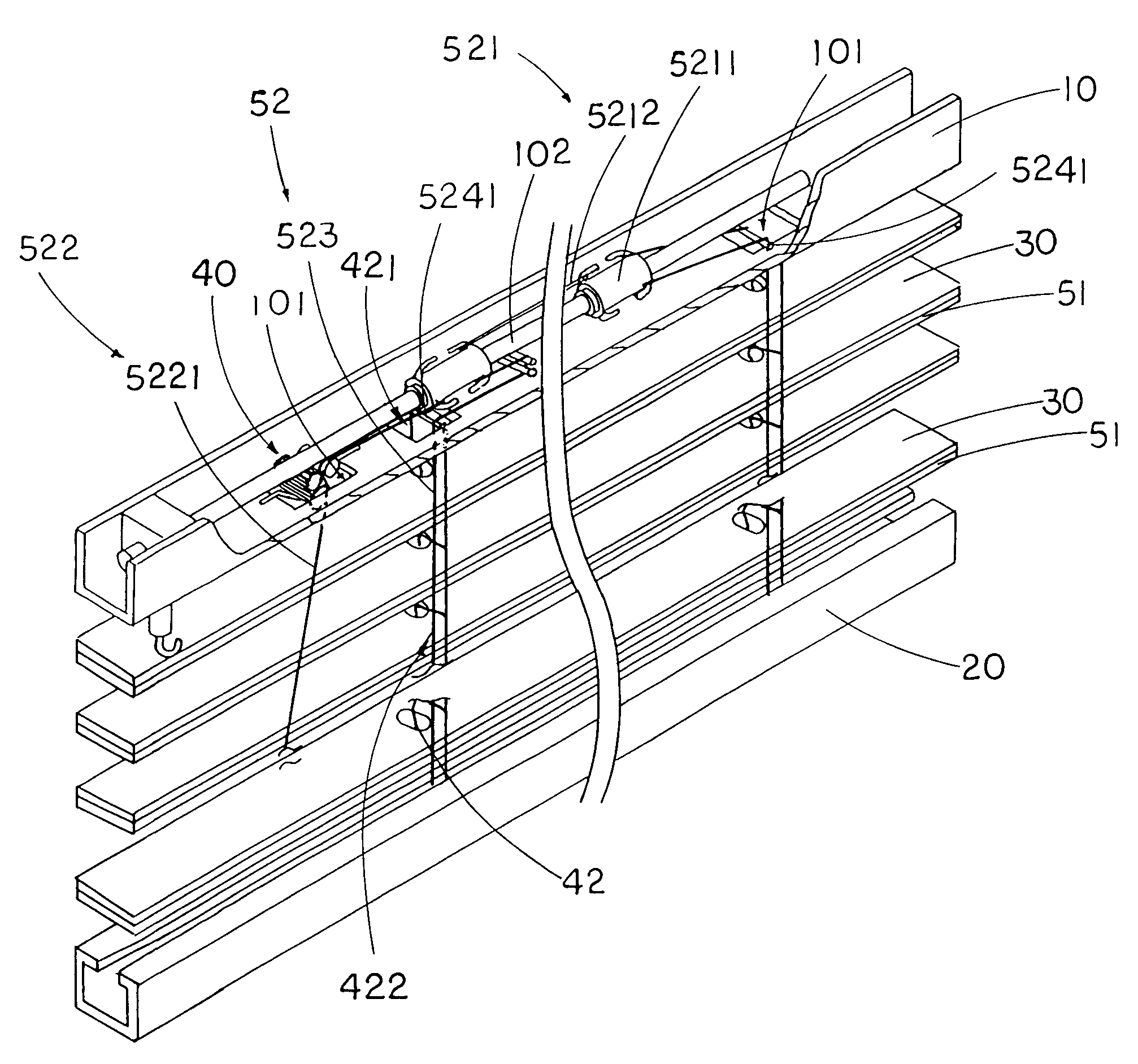
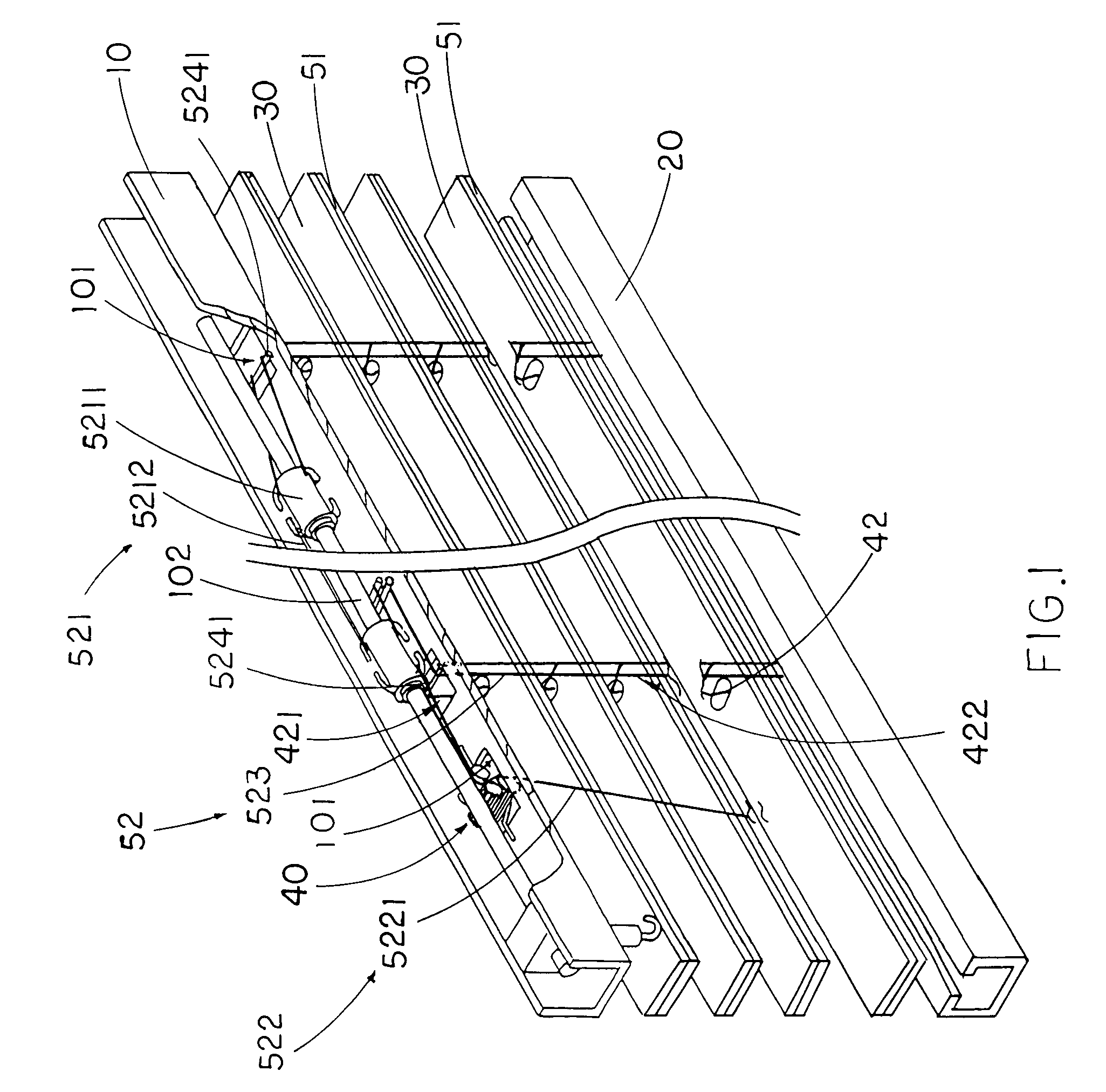
[0037]Referring to FIG. 1, a window blind according to the preferred embodiment of the present invention is illustrated. The window blind 1 comprises a top support 10 adapted for supporting at a window ceiling, a bottom support 20 spacedly disposed underneath the top support 10, and a plurality of slats 30 spacedly disposed between the top support 10 and the bottom support 20.

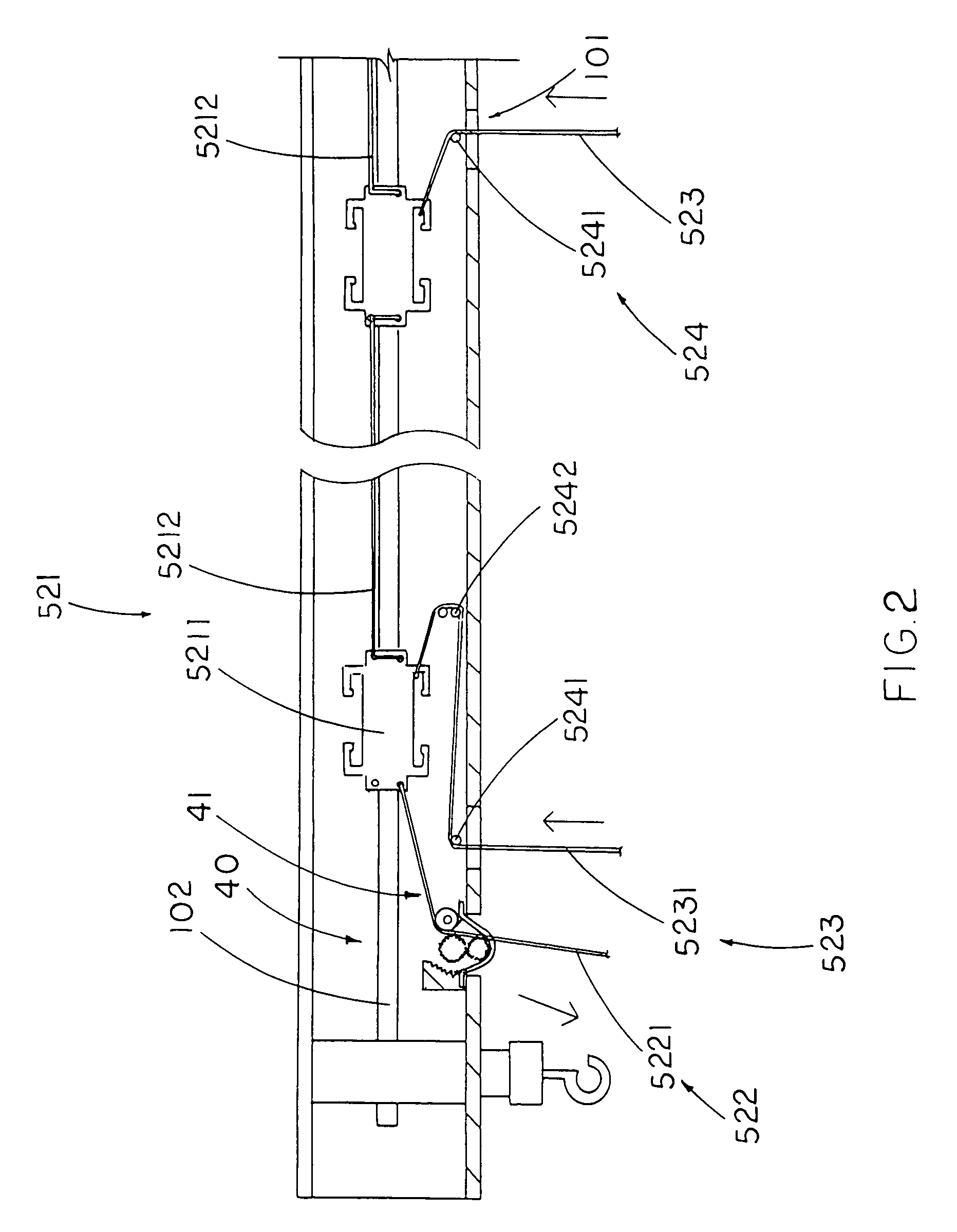
[0038]Furthermore, the window blind 1 comprises a folding unit 40 comprising a pulley system 41 supported by the top support 10 and an elongated cord 42 having a lifting portion 421 extended from the top support 10 to engage with the pulley system 41 and a folding portion 422 extended from the top support 10 to the bottom support 20 to suspendedly support the slats 30 in such a manner that when the lifting portion 421 of the elongated cord 42 is pulled from the top support 10, the bottom support 20 is lifted up towards the top support 10 to overlap with the slats 30 between the top and bottom supports 10, 20.

[0...


PUM


Abstract

A supplement blind enhancement for a window blind includes a plurality of enhancing blades positioned between every two adjacent slats of the window blind, a control system having a control slider, a blade controller extended from the control slider to slidably shift the control slider between a light shading position and a light enhancing position, and an elongated element extended from the control slider to engage with the enhancing blades. At the light shading position, the control slider is driven to slide the enhancing blades suspendedly disposed between the slats in an alternating manner for substantially blocking sunlight passing through a gap between each two slats, and at the light enhancing position, the control slider is driven to slide that each of the enhancing blades to overlap with the respective slat for allowing the sunlight passing through the gap between each two slats.

Description

BACKGROUND OF THE PRESENT INVENTION[0001]1. Field of Invention[0002]The present invention relates to window blind, more particularly, relates to a lift cord operation system for improving and smoothing out the operation of the window blind so as to provide a diversified shading effect.[0003]2. Description of Related Arts[0004]Blinds and the like such as drapes and portieres are commonly used for sheltering window, separating spaces, and etc., since they are easily maneuverable and aesthetically appealing. Most of the blind comprise a head rail, a bottom rail, a plurality of hanging nets downwardly extended from the head rail to the bottom rail for horizontally and suspendedly supporting a plurality of slats, wherein the slats could be shifted in a vertical movable manner by a lifting mechanism, and individually rotated at the same time.[0005]Here, the lift mechanism is adapted to lift the bottom rail to a desired elevation for selectively allowing the window to be exposed to an exte...

Claims


Application Information

Patent Timeline
Patent Type & Authority Patents(United States)
IPC IPC(8): E06B9/30E06B9/32
CPCE06B9/303
Inventor LAI, TONY
Owner LAI TONY
Learn More