Bioreactor for culturing microorganisms

a technology for microorganisms and bioreactors, which is applied in the direction of biomass after-treatment, specific use of bioreactors/fermenters, biochemistry apparatus and processes, etc. it can solve the problems of high cost, complex design of the enclosing end of the reactor chamber, and relatively complex complete emptying of the bioreactor, so as to avoid fluctuations in volumetric flow rate, increase flow velocity, and reduce the effect of pressure resistan

Inactive Publication Date: 2008-09-16
SARTORIUS STEDIM BIOTECH GMBH
View PDF9 Cites 24 Cited by
  • Summary
  • Abstract
  • Description
  • Claims
  • Application Information

AI Technical Summary

Benefits of technology

[0013]According to a still further preferred embodiment of the invention, the upright vessel has an open cross-sectional area which approximately corresponds to the total of all open cross-sectional areas of the gas-introduction tubes. As a result, fluctuations in volumetric flow rate can be avoided, so that low pressure resistances occur. At the same time, it has been found that, to produce the flow velocity, significantly less gas is required than in known bioreactors which operate according to the airlift principle. As a result of the circulation in the cultivation vessels, unexpected dynamics form, which contribute to increasing the flow velocity.
[0014]According to another further preferred embodiment of the invention, the gas-introduction tubes are connected via tube bends to the expansion vessel. This is firstly, simpler in terms of assembly, and secondly the flow reversal is advantageously shifted to the expansion vessel. The expansion vessel has a lid on which are disposed a media feed device and an exhaust gas apparatus having exhaust-gas cooler and exhaust-gas sensor.
[0016]According to a further embodiment of the invention, the reactor vessel is constructed as a heat exchanger. The reactor vessel has in this case a reactor lower part having an outwardly dished base. In addition, the reactor lower part has an intermediate base which is dished into the biomass chamber and which, together with the outwardly dished base, forms a heating or cooling chamber. The reactor lower part is covered by an attachment lid having attachment flanges for the gas-introduction tubes, having an attachment flange for the sensors (pH, T, pO2, optical density OD) and having an attachment flange for the upright vessel. Between attachment lid and intermediate base, the reactor lower part thus has a biomass chamber which advantageously has a smaller volume compared to the prior art and produces a turbulent flow with good mixing. The heating or cooling chamber can be heated or cooled via a heating or cooling device by feeding a heating or cooling medium, heat being exchanged between the heating or cooling chamber and the culture medium in the biomass chamber. The heating or cooling device advantageously consists of a closed hot water pressure system having a circulation pump and a heat exchanger for cooling water. The temperature of the culture medium can be used as control parameter. The reactor vessel and heat exchanger can additionally be provided with connections for an external heating or cooling circuit. By means of the chosen heat exchanger, firstly in a growth phase, a constant temperature can be maintained, and secondly, for initiating a stress phase for producing material of value, an elevated temperature can be achieved without problem and rapidly. Cooling is also possible in this manner without problems.

Problems solved by technology

It is a disadvantage that such a design of the enclosing ends of the reactor chamber is very complex and cost intensive.
It is a disadvantage of the known bioreactor that, owing to the arrangement of the U-shaped reactor elements, complete emptying of the bioreactor is relatively complex, since each of the reactor elements must be emptied separately.

Method used


Image

  • Bioreactor for culturing microorganisms
  • Bioreactor for culturing microorganisms
  • Bioreactor for culturing microorganisms

Examples


Embodiment Construction

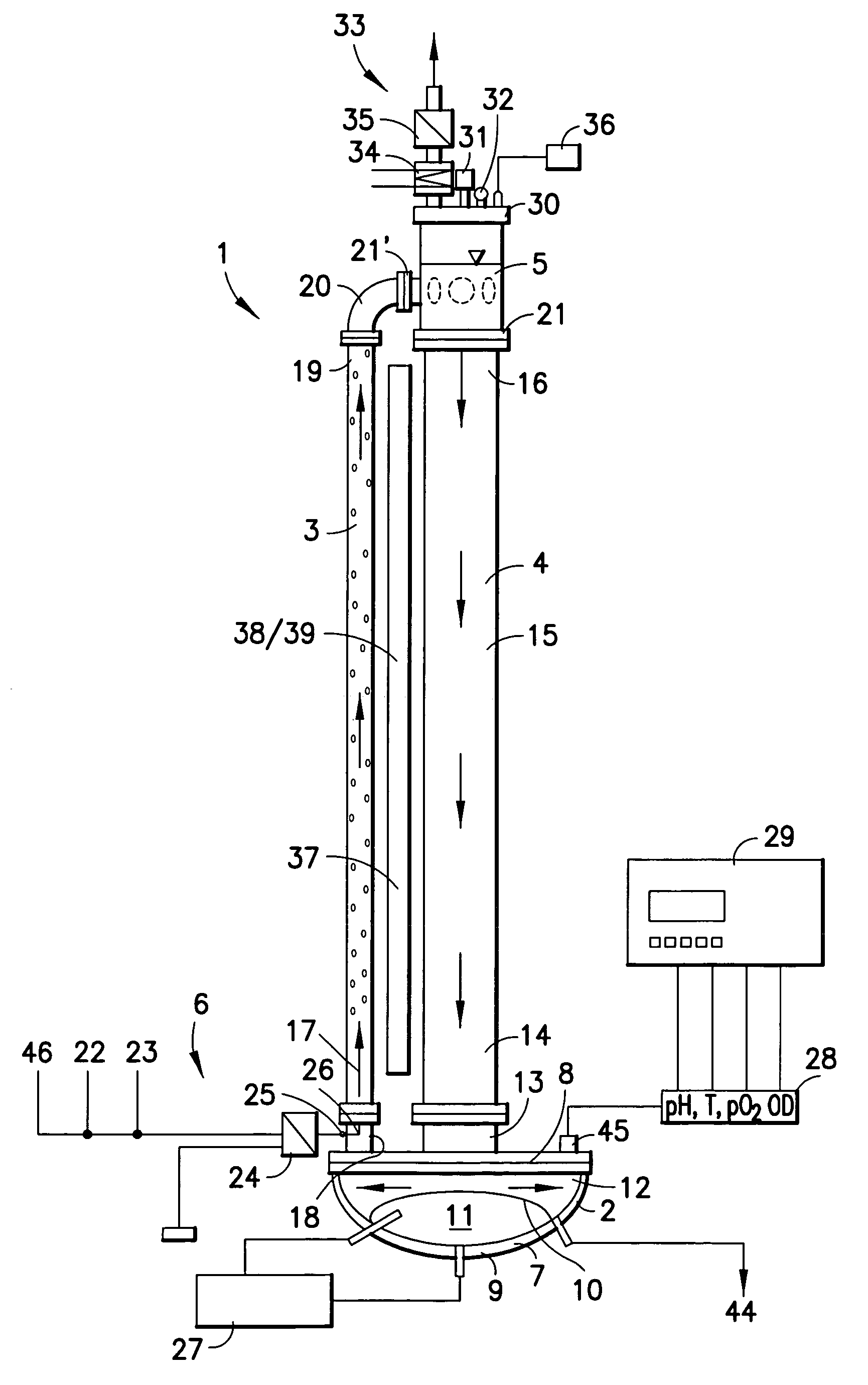
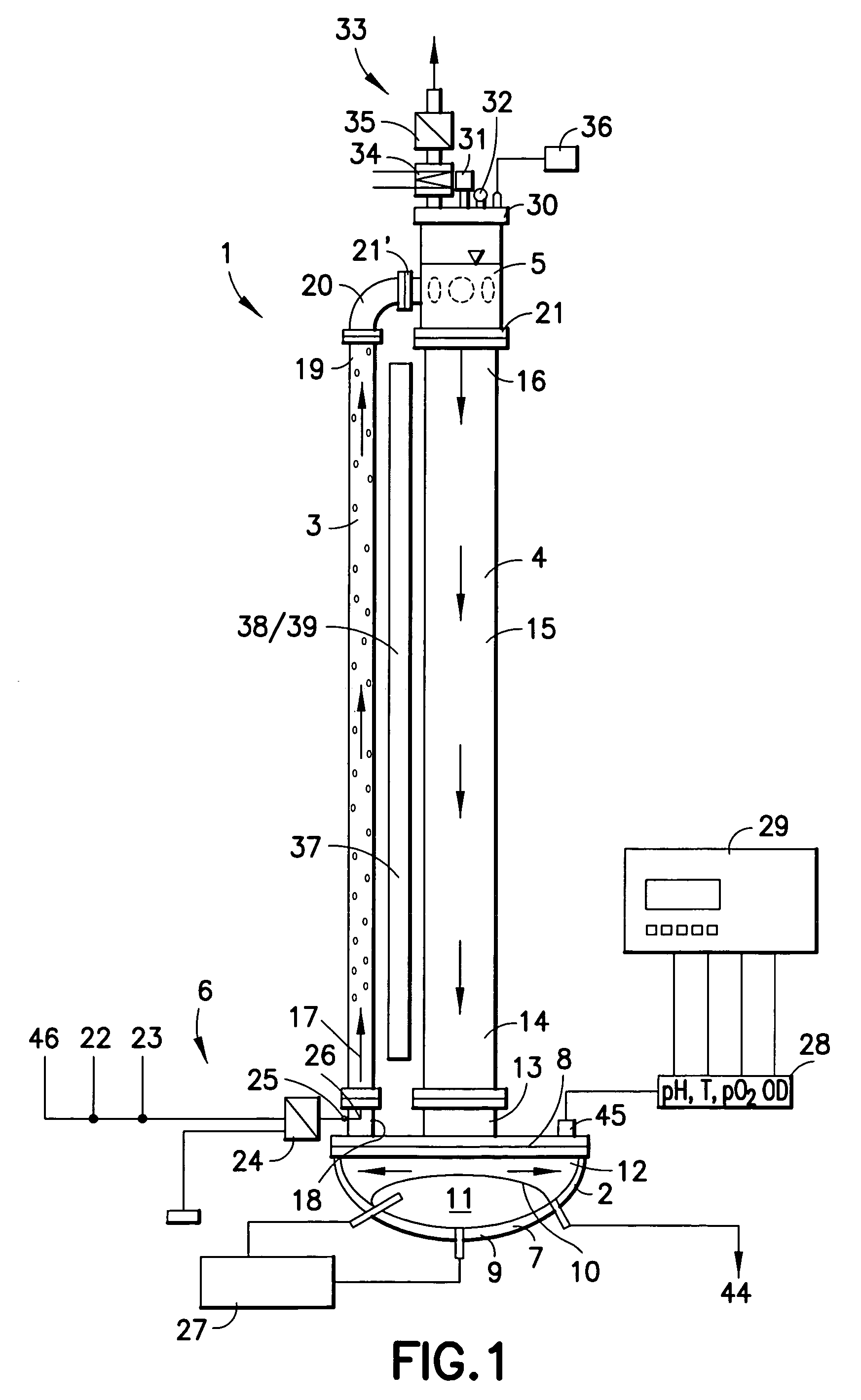
[0023]A bioreactor 1 for the culture of phototropic microorganisms essentially consists of a reactor vessel 2, gas-introduction tubes 3, an upright vessel 4, an expansion vessel 5 and a gas-introduction system 6.

[0024]The reactor vessel 2 is constructed as a heat exchanger and consists of a reactor lower part 7 which is covered gas-tightly at the top, in the vertical direction, by an attachment lid 8. The reactor lower part 7 has an outward-dished base 9 and an inner-dished intermediate base 10. A heating or cooling chamber 11 is enclosed by the intermediate base and the base 9. The chamber enclosed by the base 9, intermediate base 10 and attachment lid 8 forms a biomass chamber 12. The reactor vessel 2 is designed as a jacketed stainless steel vessel and serves for heat transfer, measurement determination, and media removal (harvest material, wastewater) and sampling.

[0025]A harvest and base outlet valve 44 is built into the lowest part of the reactor vessel 2. It can be used for s...


PUM

PropertyMeasurementUnit
pressureaaaaaaaaaa
transparentaaaaaaaaaa
areaaaaaaaaaaa

Abstract

A bioreactor for culturing microorganisms which has a reactor vessel, a plurality of gas-introduction tubes and a gas-introduction system for introducing gas into a culture medium in the gas-introduction tubes via injectors, wherein the gas-introduction tubes are connected by their respective lower end, in the vertical direction, to the reactor vessel and by their opposite upper end to the upper end of an upright vessel which is likewise connected by its lower end to the reactor vessel, and at the upper end of the upright vessel an expansion vessel is arranged.

Description

BACKGROUND OF THE INVENTION[0001]1. Field of the Invention[0002]The invention relates to a bioreactor for culturing microorganisms which has a reactor vessel, a plurality of gas-introduction tubes and a gas-introduction system for introducing gas into a culture medium in the gas-introduction tubes via injectors.[0003]2. Description of the Related Art[0004]It is known to use photobioreactors for culturing phototropic microorganisms, in particular for producing microalgae. For example, WO 00 / 61719 discloses that a high biomass productivity is a problem of optimum light distribution per unit volume. The known bioreactor has a reactor compartment made of translucent material, the enclosing end of which of the reactor chamber cross section is designed, for example, in a meander shape or sinusoidally to increase the surface area. Also, this publication discloses constructing the reactor chamber as glass tube into the interior of which project glass extensions.[0005]It is a disadvantage th...

Claims


Application Information

Patent Timeline
Patent Type & Authority Patents(United States)
IPC IPC(8): C12M1/42C12M1/04C12M1/08
CPCC12M21/02C12M23/44C12M29/18C12M29/22C12M41/36C12M41/12C12M41/18C12M41/26C12M41/34C12M31/02
Inventor BRONESKE, JURGENFRANKE, HORSTPULZ, OTTOKEITEL, HEINZ-RUDIGERLINKE, WOLF-DIETRICHWILHELM, BERND-ULRICHSALZMANN, RAINERKROGER, WOLFGANGRIESE, MIRKO
Owner SARTORIUS STEDIM BIOTECH GMBH
Why Eureka
Try Eureka