
Charge apparatus of an extension cord plug

a technology of charging apparatus and extension cord, which is applied in the direction of emergency power supply arrangement, safety/protection circuit, coupling device connection, etc., can solve the problems of not having additional functions, providing plugs to alternating-current electronic devices, and conventional apparatus still has many drawbacks, and achieves high-efficiency feedback

Inactive Publication Date: 2008-09-16
LAI LI CHUN
View PDF6 Cites 22 Cited by
  • Summary
  • Abstract
  • Description
  • Claims
  • Application Information

AI Technical Summary

Benefits of technology

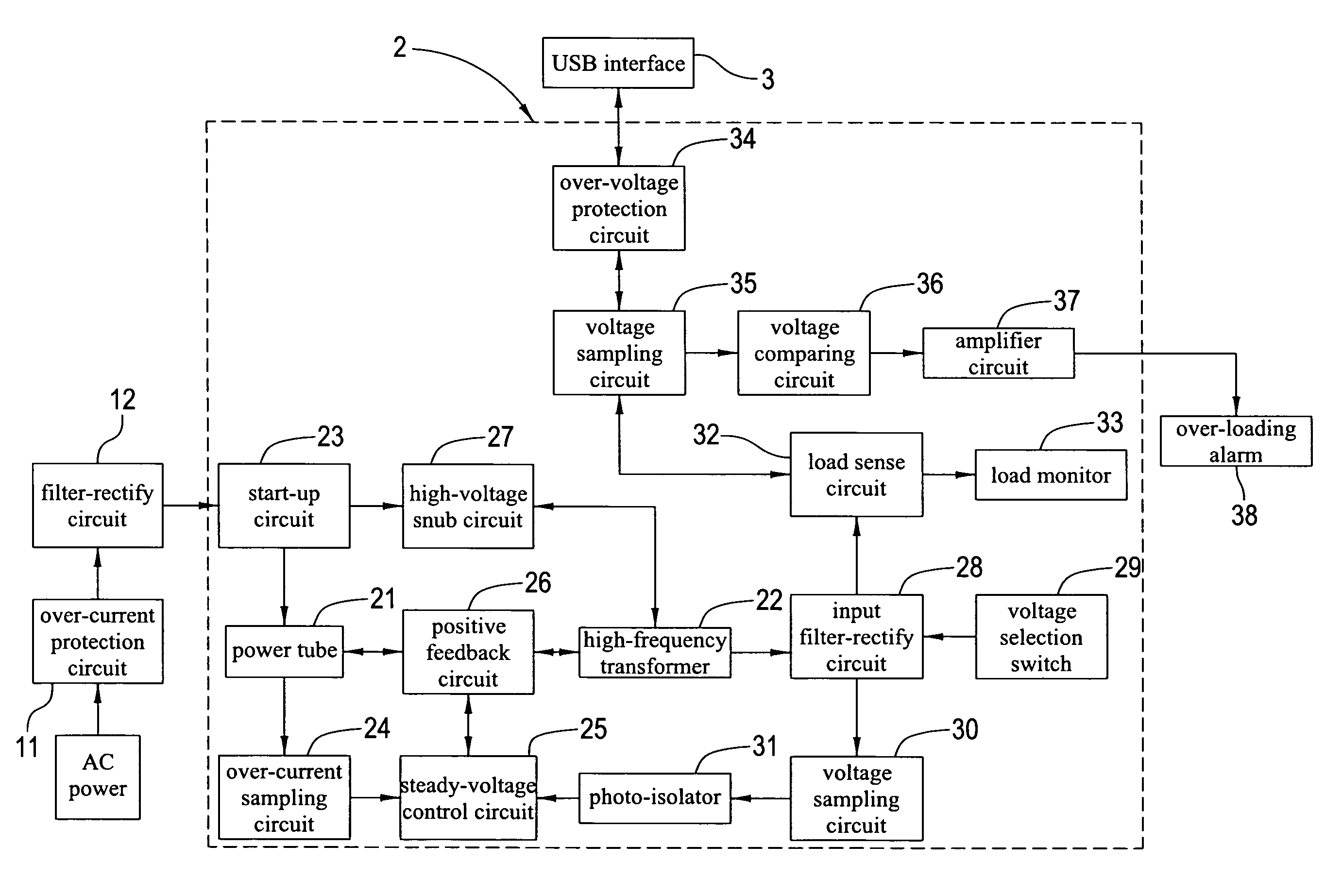
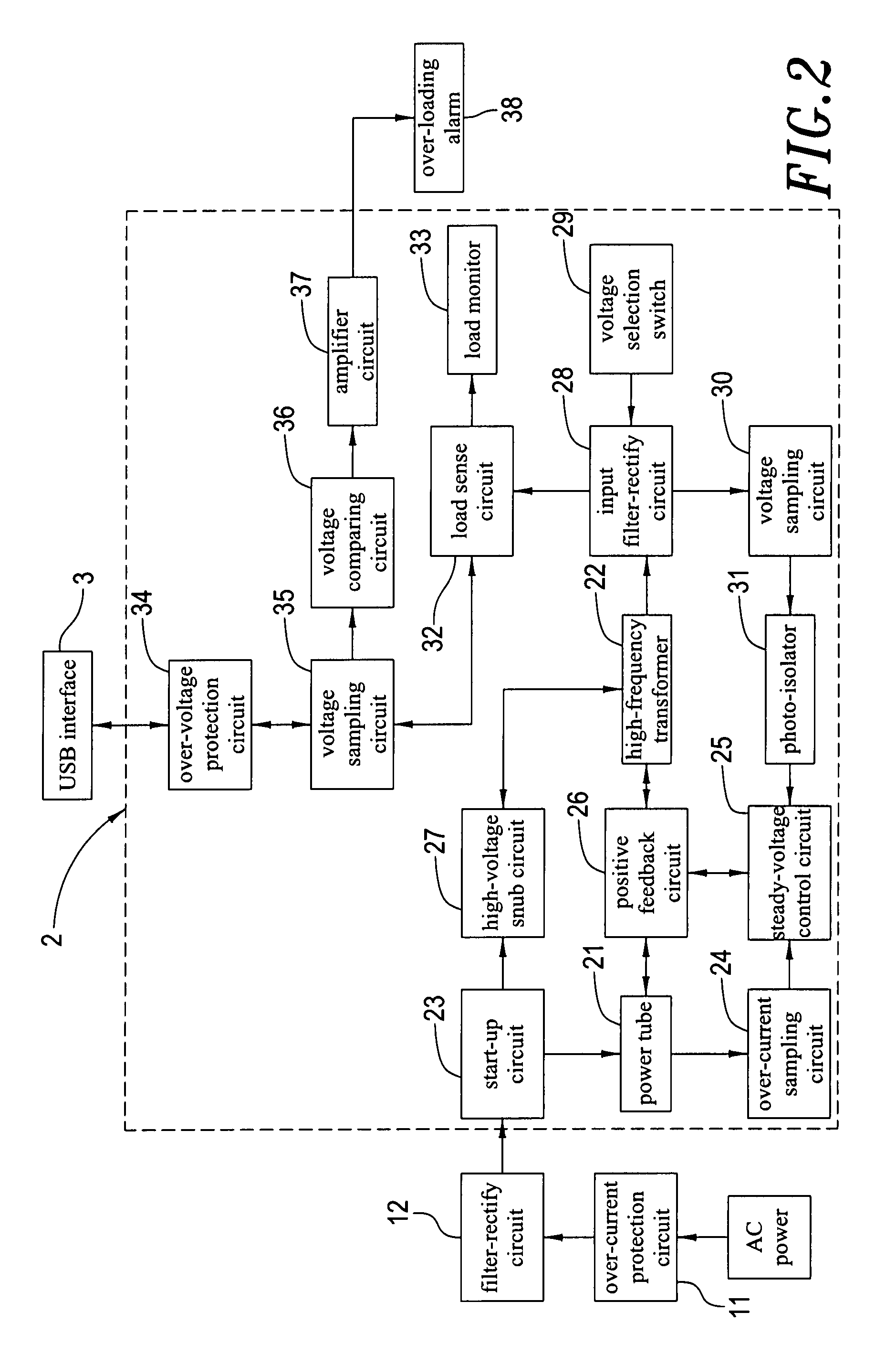
"The invention provides a charge apparatus inside an outlet that can be connected to a USB interface outside the outlet to charge devices through the USB interface. The charge apparatus has various charging voltage sources that users can select for different devices. The charge apparatus has a start-up circuit, a high-voltage snub circuit, a power tube, an over-current sampling circuit, a steady-voltage control circuit, a positive feedback circuit, a high-frequency transformer, an output filter-rectify circuit, an output voltage sampling circuit, a voltage selection switch, a photo-isolator, a load sense circuit, and a load monitor. The invention has features such as over-current protection, filtering and rectification of input AC power, control of power tube output voltage, and high-frequency transformer output voltage filtering and rectification. The load monitor senses whether there is any load connected to the USB interface and emits light accordingly. The technical effects of the invention include efficient and low-interference charging of devices through the USB interface and flexibility in selecting different charging voltage sources for different devices."

Problems solved by technology

Although the extension cord plug is practical, it can only provide plugs to alternating-current electronic devices but have no additional functions.
It can be tell that the conventional apparatus still has many drawbacks and is not good in design, thus the conventional apparatus needs improvement.

Method used


Image

  • Charge apparatus of an extension cord plug
  • Charge apparatus of an extension cord plug
  • Charge apparatus of an extension cord plug

Examples


Embodiment Construction

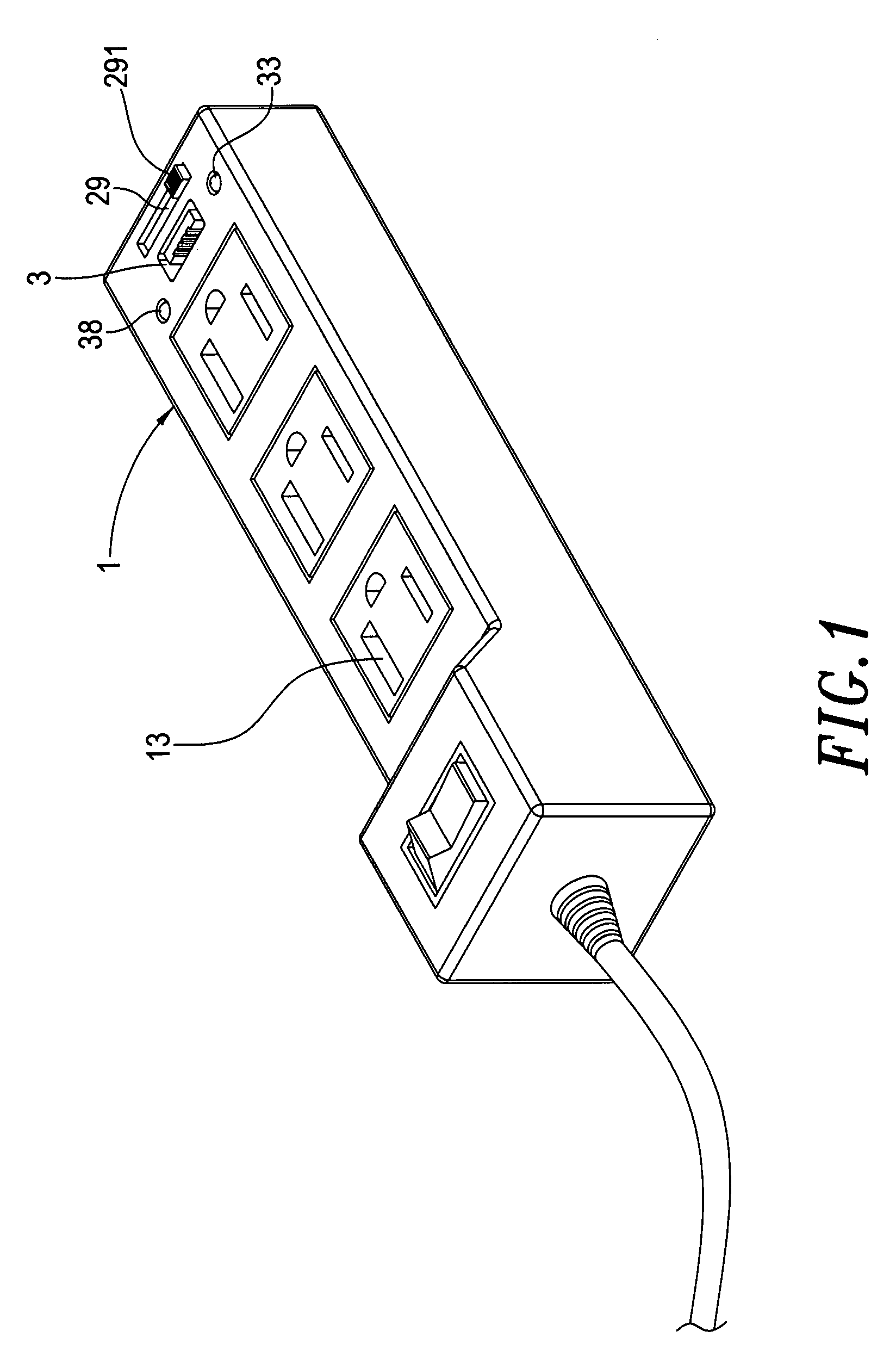
[0018]Referring to FIGS. 1-3, in which the charge apparatus of an extension cord plug of the present invention is shown. An extension cord plug of the present invention mainly comprises an outlet 1, a charge apparatus 2, and an USB interface 3.

[0019]The outlet 1 is configured with a plug 13 outside the surface of the outlet 1, and internally configured with an over-current protection circuit 11 and a filter-rectify circuit 12. The over-current protection circuit 11 is configured to sense whether there is any short-circuit or abnormal status around the whole circuitry to prevent damaging the whole circuitry. The filter-rectify circuit 12 is configured to filter and rectify the inputted AC current and provide a steady DC current to a charge apparatus 2, and the over-current protection circuit 11 may be a fuse.

[0020]The USB interface 3 is outside the outlet 1 and connected to the charger 2.

[0021]The charge apparatus 2 comprises a power tube 21, a start-up circuit 23, a over-circuit sam...


PUM


Abstract

A charge apparatus of an extension cord plug is provided. The charge apparatus is set inside an outlet and connected to an USB interface outside the outlet. When the outlet is electrified, the plug thereon is able to provide power to an electric appliance for normal operation through the USB interface after processing of the charge apparatus. By the time, the user may select demanded voltage to achieve objective of charging by various voltage sources.

Description

BACKGROUND OF THE INVENTION[0001]1. Field of the Invention[0002]The present invention relates to a charge apparatus of an extension cord plug. More particularly, the present invention relates to a charge apparatus with an USB charge interface outside an outlet for user to charge electronic devices.[0003]2. Descriptions of the Related Art[0004]Extension cord plugs are widely used with frequency, due to its character of supplying insufficient plugs at home or working place for indoor electronic devices, such as lamps that hang on the tree, or outdoor workers. Therefore, extension cord plugs are almost daily necessaries for every family.[0005]Although the extension cord plug is practical, it can only provide plugs to alternating-current electronic devices but have no additional functions. Since the utility rate of the extension cord plug is high, the extension cord plug still needs improvement.[0006]It can be tell that the conventional apparatus still has many drawbacks and is not good...

Claims


Application Information

Patent Timeline
Patent Type & Authority Patents(United States)
IPC IPC(8): H02M1/00
CPCH02J7/022H02J7/027H02J7/0042H01R24/66H01R25/003H01R31/065H01R2103/00H02J2009/007H02J2007/0062H02J9/007H02J7/02H02J2207/20H02J7/00308H02J7/0047H02J7/00304H02J7/00
Inventor LAI, LI-CHUN
Owner LAI LI CHUN
Learn More