Systems and methods for monitoring speed

a technology of system and method, applied in the field of systems and methods for measuring the speed of a vehicle, can solve the problems of difficult and expensive monitoring of the speed of vehicles using people, the hardware required to implement this method can introduce significant cost, and the device relying on the doppler shift cannot distinguish between vehicles, so as to avoid errors

Active Publication Date: 2008-09-16
WAVETRONIX
View PDF79 Cites 54 Cited by
  • Summary
  • Abstract
  • Description
  • Claims
  • Application Information

AI Technical Summary

Benefits of technology

[0016]Two laterally separated transducers can be used to measure the speed of a vehicle in a dual transducer sensor configuration. Dual transducer configurations are particularly suited for side fire configurations but can also be designed to perform well in off angle configurations. In this case, the speed of the vehicle is proportional to the delay between the signals received by the respective signals. The fields of view of the sensors typically overlap and the sensors generate similar signals. This avoids errors that would otherwise be introduced by dissimilar signals. Also, the direction of the vehicle can be determined from the sign of the time delay between the signals of the two sensors.

Problems solved by technology

However, monitoring the speed of vehicles using people is difficult and expensive.
The hardware required to implement this method can introduce significant cost.
This method can potentially result in erroneous results if the laser is swept along the side of the vehicle as the distance measurements are taken.
However, devices relying on the Doppler shift cannot distinguish between vehicles and cannot determine the range to a particular vehicle.
These methods are often inaccurate as the signals returned by the respective zones are often dissimilar as previously mentioned.
The primary disadvantage of this method is that the inductive loops are difficult and expensive to install and maintain.
In addition to being costly, installing and maintaining the inductive loops typically interferes with traffic.

Method used


Image

  • Systems and methods for monitoring speed
  • Systems and methods for monitoring speed
  • Systems and methods for monitoring speed

Examples


Embodiment Construction

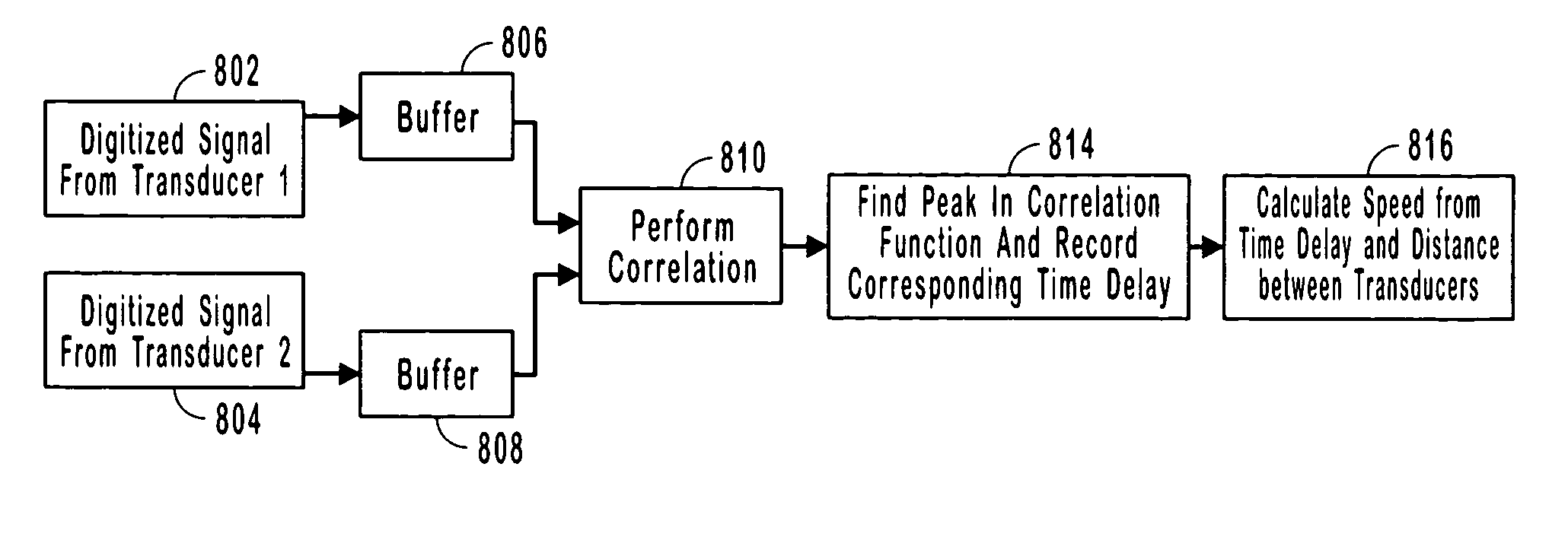
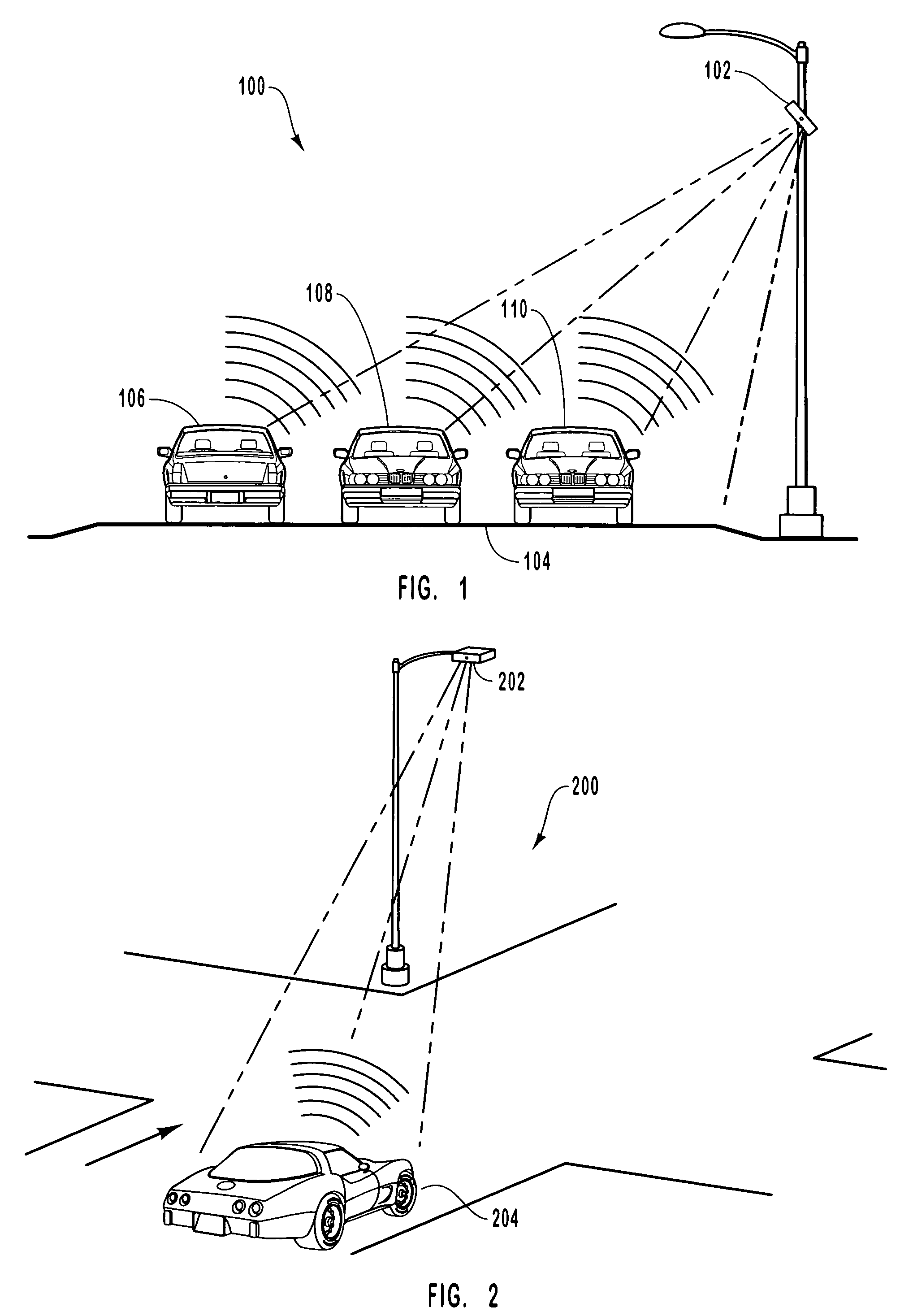
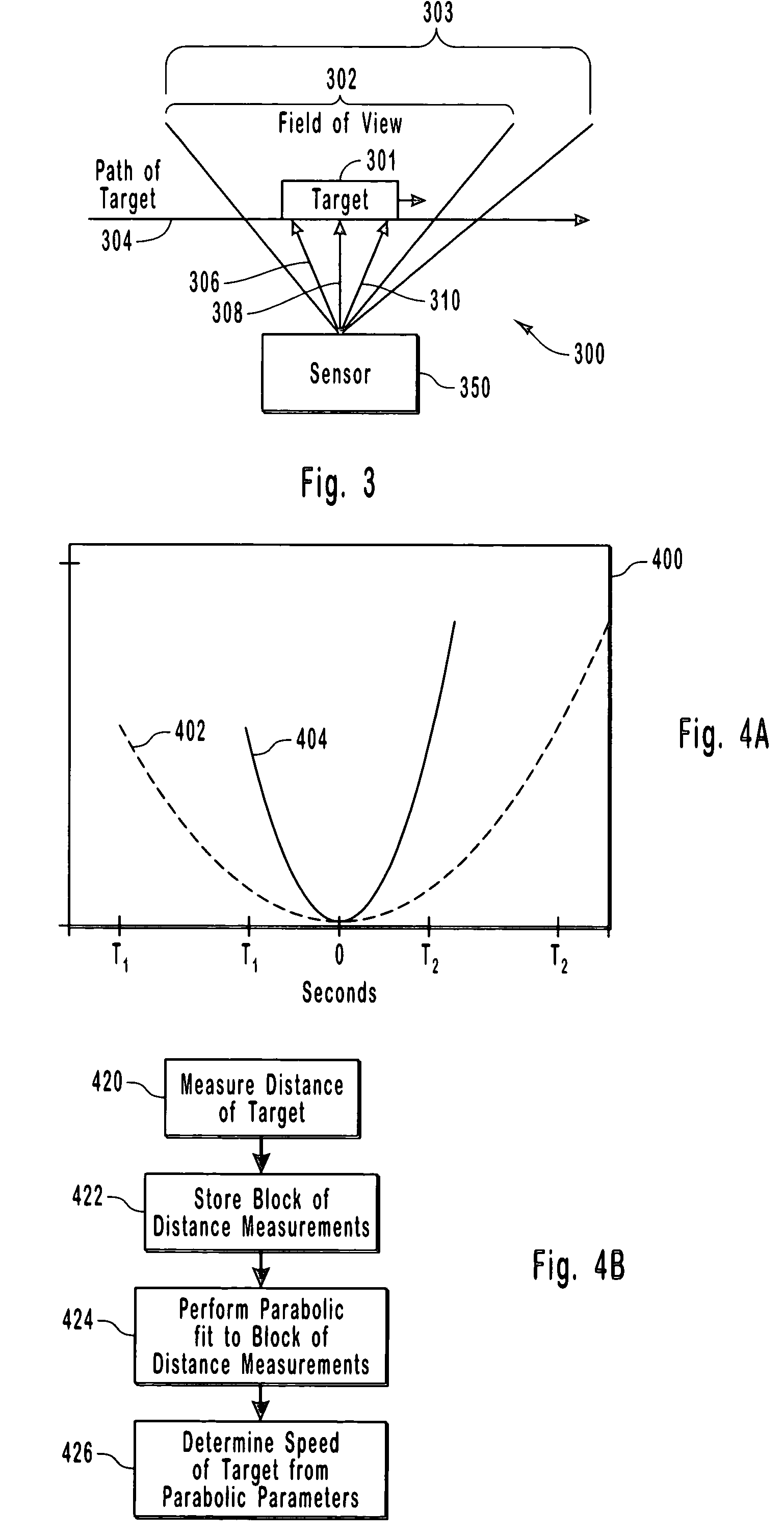
[0037]The present invention relates to systems and methods for measuring the speed of a target such as a vehicle on a roadway. As described in more detail below, the present invention measures the speed of a vehicle using a single transducer side fire sensor configuration, a dual transducer sensor configuration, or a forward fire sensor configuration. In some alternative embodiments, both the side fire sensor configuration, the dual transducer sensor configuration, and the forward fire sensor configuration can use multiple transducers. The speed is measured by using the sensor to receive a signal from the targets in the field of view of the sensor. The signal received by the sensor(s) could be a reflection of a signal transmitted by the sensor(s) towards the targets in a field of view or alternatively, the signal could be an emission from the target itself. The signal(s) generated and received by the sensor(s) are used to measure distance, phase change, Doppler shift, and the like. ...


PUM


Abstract

Systems and methods for measuring the speed and / or direction of a target such as a vehicle in a field of view. The speed of a vehicle is measured using distance measurements, phase measurements, or Doppler shift measurements using a single transducer side fire configured sensor. The speed of a vehicle can be measured using laterally spaced transducers in a side fire or off angle configuration and using a single transducer sensor in a forward fire configuration.

Description

RELATED APPLICATIONS[0001]This application claims the benefit of U.S. Provisional Application Ser. No. 60 / 439,109, filed, Jan. 10, 2003 and entitled SYSTEMS AND METHODS FOR DETERMINING THE VELOCITY OF A TARGET which is hereby incorporated by reference.BACKGROUND OF THE INVENTION[0002]1. The Field of the Invention[0003]The present invention relates to systems and methods for monitoring traffic. More particularly, the present invention relates to systems and methods for measuring the speed of a vehicle and more specifically to systems and methods for measuring the speed of a vehicle using different sensor configurations.[0004]2. Background and Relevant Art[0005]As the number of vehicles on roadways increases and traffic becomes more congested, monitoring existing traffic and planning for future traffic become more important. Monitoring traffic in particular has received increasing attention from traffic planners. The information gathered from monitoring various aspects of traffic is u...

Claims


Application Information

Patent Timeline
Patent Type & Authority Patents(United States)
IPC IPC(8): G01P5/00G01P11/00G01S13/58G01S13/87G01S13/92G08G1/052
CPCG01S13/583G01S13/588G08G1/052G01S13/92G01S13/87
Inventor ARNOLD, DAVID V.DOUGALL, JR., JOHN B.GILES, BRADLEY CURTISJARRETT, BRYAN ROBERTKARLINSEY, THOMAS WILLIAMWAITE, JONATHAN L.
Owner WAVETRONIX
Why Eureka
Try Eureka