
Gap adjusting device, recording apparatus and liquid ejection apparatus

a technology of adjusting device and recording apparatus, which is applied in the direction of printing mechanism, power drive mechanism, printing, etc., can solve the problems of large number of components, large apparatus size, and difficulty in designing a layout for securing the operation area

Inactive Publication Date: 2008-09-23
SEIKO EPSON CORP
View PDF3 Cites 6 Cited by
  • Summary
  • Abstract
  • Description
  • Claims
  • Application Information

AI Technical Summary

Benefits of technology

The solution simplifies the device configuration, prevents positional displacement in the sub scanning direction, and eliminates rotation phase lag, enabling high precision recording by allowing the carriage to move up and down in parallel, thus facilitating easier design and operation.

Problems solved by technology

However, in a paper gap adjusting device with such the configuration, it becomes such a complex configuration that a rotary motion of the drive motor is converted into a linear motion, and further, converted again into a rotary motion through the link mechanism, and therefore, the number of components becomes large, and the apparatus grew in size.
Particularly, in the rack and pinion mechanism and the link mechanism, an operation area of a linear motion portion becomes large-by any mechanisms, and therefore, it makes it difficult to design a layout for securing the operation area.
However, in a paper gap adjusting device with such the configuration, in order to enlarge a changing amount of the paper gap, there is such a necessity that an eccentricity amount of the carriage guide shaft is enlarged (which leads up to increase of a shaft diameter of the carriage guide shaft), or a rotation angle of the carriage guide shaft is enlarged, and there is structural limitation of the carriage guide shaft.
In addition, when an eccentricity amount of the carriage guide shaft is enlarged, the carriage guide shaft moves in not only up and down directions, but also back and forth directions (a paper carrying direction or a sub scanning direction), and therefore, a land-in position of an ink droplet becomes out of alignment, and it becomes impossible to perform high precision recording.

Method used


Image

  • Gap adjusting device, recording apparatus and liquid ejection apparatus
  • Gap adjusting device, recording apparatus and liquid ejection apparatus
  • Gap adjusting device, recording apparatus and liquid ejection apparatus

Examples


embodiment

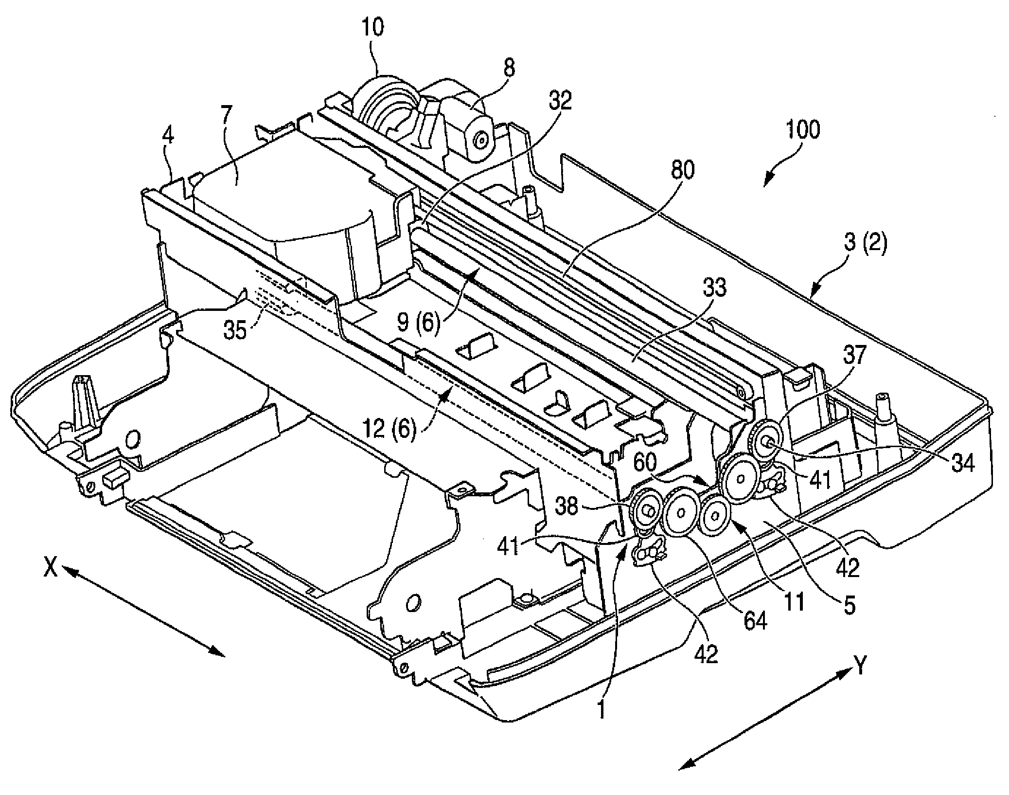
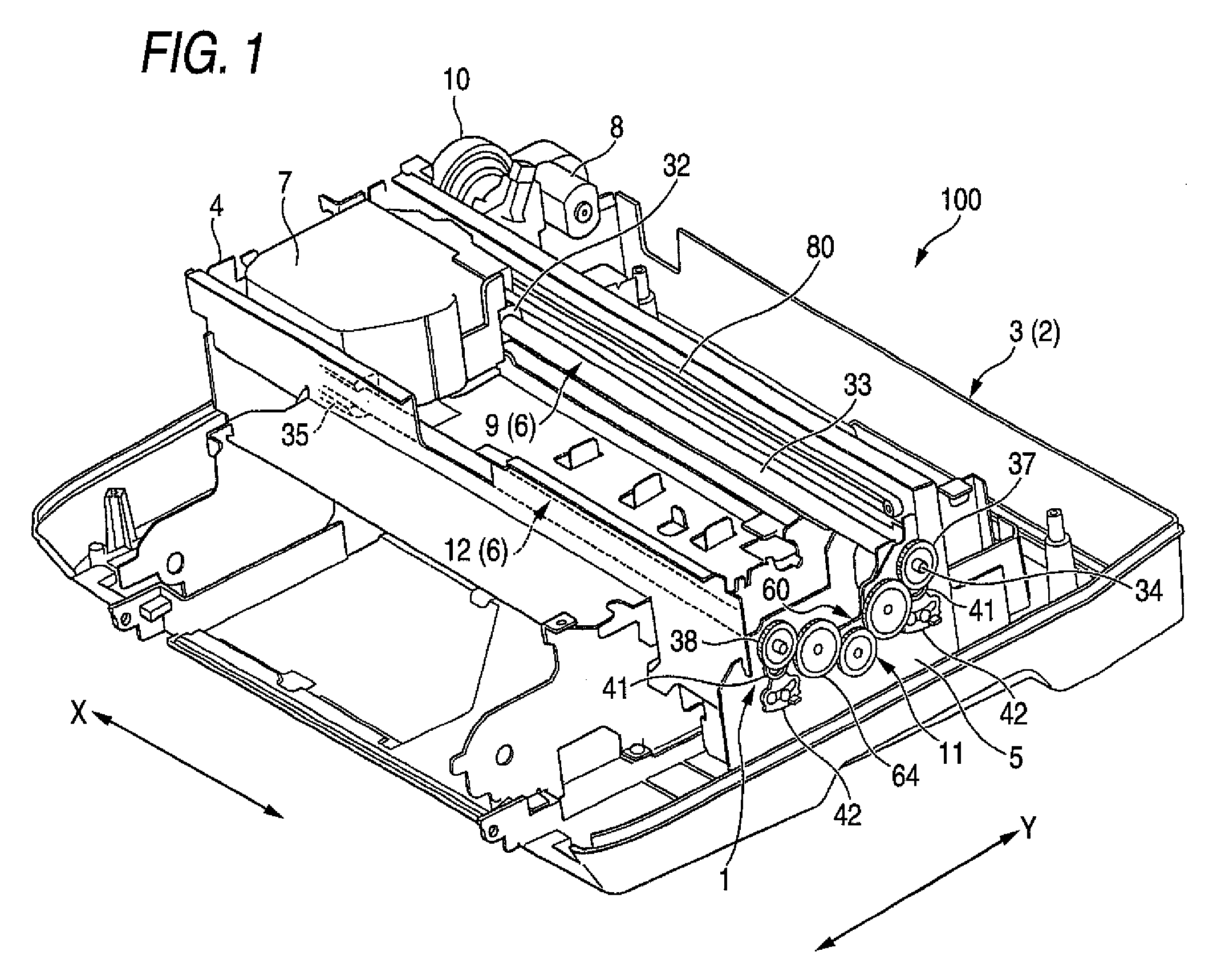
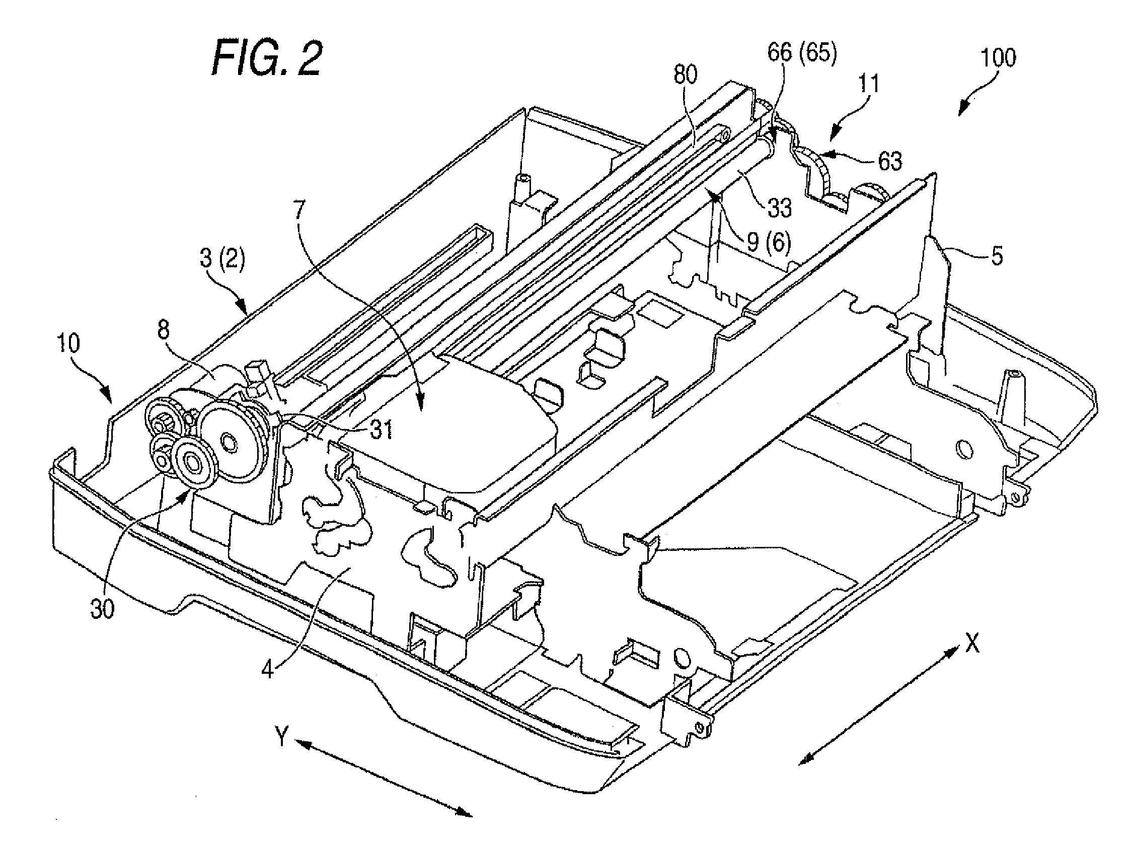
[0093]Next, a configuration of the gap adjusting device 1 which is applied to such the ink jet printer 100 and relates to the invention will be described in more detail. FIG. 4 is a perspective view showing the side frame on the right side in such a state that a synchronous drive transmission mechanism was attached thereto, and FIG. 5 is a perspective view showing the side frame on the right side in such a state that a synchronous drive transmission mechanism was attached thereto. FIG. 6 is a perspective view showing start end side drive transmission means, and FIG. 7 is an explanatory view showing cam operations of a shift cam and a cam follower. In addition, FIG. 8 is a cam diagram showing a relation of a paper gap and a rotation angle of a carriage guide shaft.

[0094]Rotation of an output shaft of the lifting drive motor 8 is transmitted to the main guide shaft 9 by start end side drive transmission means 10 which is configured by a gear wheel train 30 as shown in FIG. 6. In midst...


PUM


Abstract

It is provided with a pair of carriage guide shafts, and the carriage guide shaft is made to be in sliding contact with a carriage, to realize such a concentric shaft configuration that a guide shaft part, which directly guides a reciprocating motion of the carriage, and rotation shaft parts, which are disposed on both ends thereof, were disposed so as to coincide therewith. In addition, by disposing parallel lifting device which utilized a cam mechanism and a lifting guide portion to side frames, the carriage guide shaft is configured so as to be able to obtain a predetermined lifting stroke which corresponds to a rotation angle. In addition, as synchronous drive transmission mechanism of the pair of carriage guide shafts, a gear wheel train was used.

Description

BACKGROUND OF THE INVENTION[0001]1. Field of the Invention[0002]This invention relates to a gap adjusting device which is disposed in a recording apparatus being provided with a recording head which performs recording on a recording medium, a platen which is disposed in opposition to the recording head and defines a gap between a head surface of the recording head and the recording medium, a carriage on which the recording head is mounted and which reciprocates in a main scanning direction, and a pair of carriage guide shafts which guide a reciprocating motion of the carriage, and a recording apparatus which was provided with the adjusting device.[0003]Further, the invention relates to a liquid ejection apparatus such as an ink jet recording apparatus, which discharges (ejects) liquid such as ink from its head and performs recording on a recording medium (a medium to which liquid is ejected), and a gap adjusting device which is disposed in the liquid ejection apparatus.[0004]Here, t...

Claims


Application Information

Patent Timeline
Patent Type & Authority Patents(United States)
IPC IPC(8): B41J25/308
CPCB41J25/308
Inventor NAKAMURA, KAZUHISAHASHII, KAZUHIROMOKUO, TOMOYUKIYAMAGUCHI, KAZUHIKO
Owner SEIKO EPSON CORP
Learn More