Apparatus and method of using LED light sources to generate a unitized beam

a technology of led light source and unit beam, which is applied in the direction of instruments, lighting and heating apparatus, fibre light guides, etc., can solve the problems of high cost, poor optical performance of conventional fiber devices with or without leds, and high initial investment cost of led illumination. achieve the effect of large combined color light spectrum

Inactive Publication Date: 2008-09-23
ILLUMINATION MANAGEMENT SOLUTIONS
View PDF10 Cites 33 Cited by
  • Summary
  • Abstract
  • Description
  • Claims
  • Application Information

AI Technical Summary

Problems solved by technology

The initial investment cost of LED illumination is very expensive when compared with traditional lighting means using cost per lumen as the metric.
While this may change over time, this high cost places a premium on collection and distribution efficiency of the LED optical system.
However, the optical performance of conventional Fiber Devices, with or without LEDs, is often less than satisfactory.
This can result in over 50% efficiency loss.
Prior art techniques in LED technology suffer a different problem, however.
In a reflector based system, only a single LED can be collected at high efficiency, so the device is limited in scope.
Again the optical path ways are long, the optical system is necessarily physically large and the overall performance is still subject to intensity and collimation losses.

Method used


Image

  • Apparatus and method of using LED light sources to generate a unitized beam
  • Apparatus and method of using LED light sources to generate a unitized beam
  • Apparatus and method of using LED light sources to generate a unitized beam

Examples


Embodiment Construction

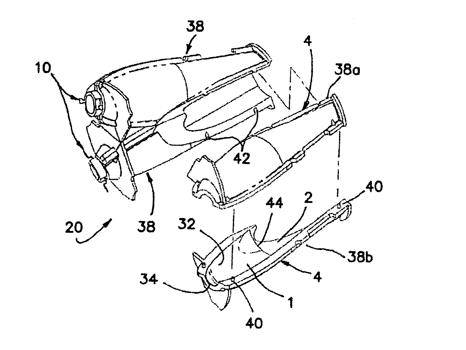
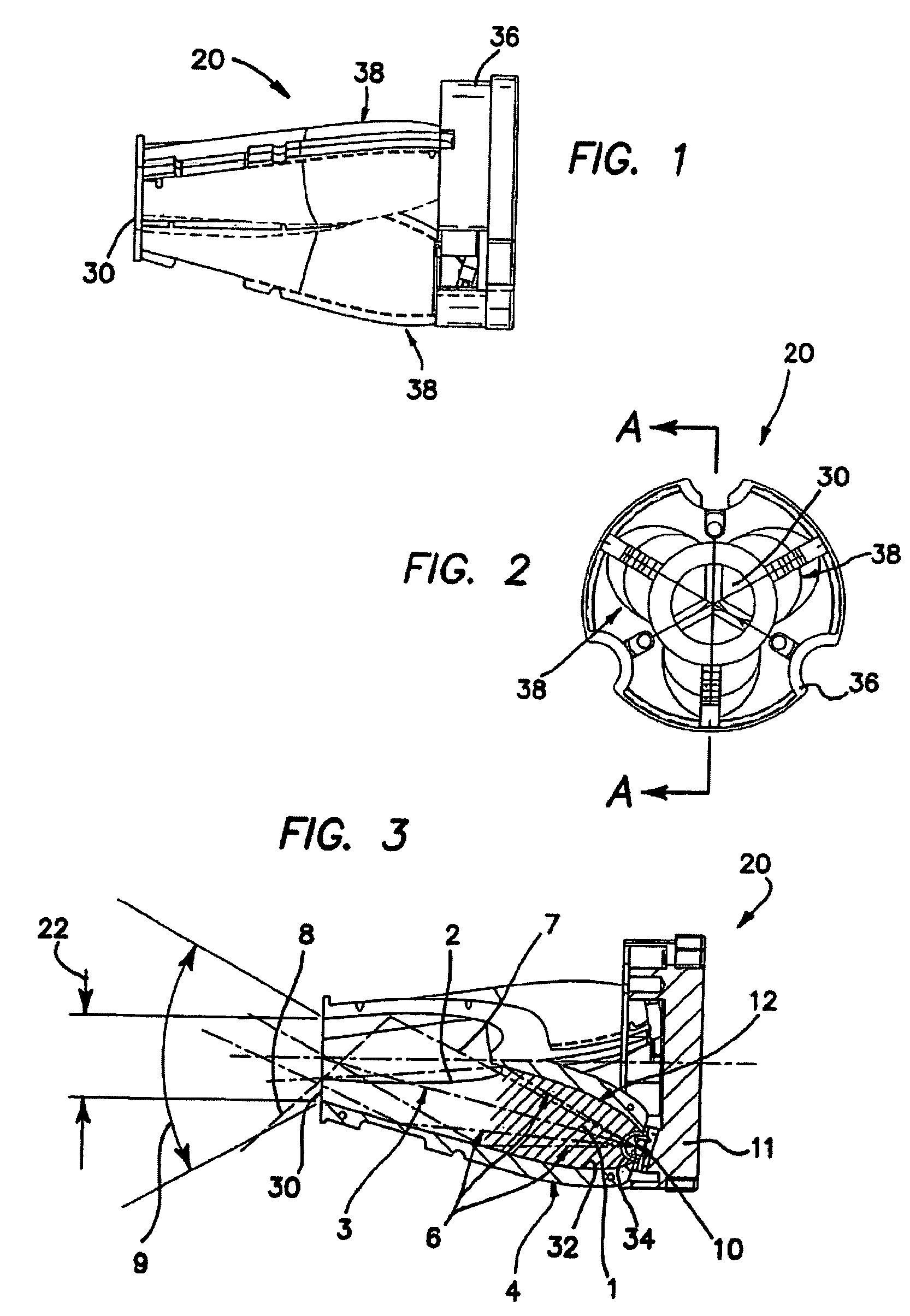
[0032]Turn to FIGS. 1-3 wherein the illustrated embodiment of the optical portion of the invention is depicted. FIG. 1 is a side elevational view of the assembled device, generally denoted by reference numeral 20, which is comprised of an assembly of various optical elements described below. In the illustrated embodiment device 20 is comprised of a common base 36 into which three lighting elements 38 are mounted. Base 36 includes a mounting platform for LEDs 10, a thermal heat sink 11, related electrical connections (not shown) to LEDs 10 and a conventional mechanical means of affixation for device 20. The three lighting elements 38 are better shown apart from base 36 in FIG. 4 where one of the three lighting elements 38 is illustrated in exploded disassembled view from the other two lighting elements 38. In the preferred embodiment each lighting element 38 is comprised of two molded halves 38a and 38b, which snap fit together or may be adhered to each other and aligned through conv...


PUM


Abstract

An apparatus includes: a plurality of light emitting diodes (LED) of similar or differing wavelengths; a reflector for collecting energy from two or more LEDs into an approximately composite beam; and a housing for distributing this energy into a common aperture. A heat sink and electronic control for the individual LEDs is included. The LEDs have different color outputs and are selectively controlled to determine the color of light from the apparatus. In one embodiment there are at least two LEDs, at least two reflector cavities, a common combining cavity or zone, a mounting each of the LEDs within the reflector cavities and a housing. The LEDs are mounted on the heat sink And selectively driven to modulate the intensity of selected ones of the LEDs according the nature of the frequency bands in the driving signal, e.g. mixed color outputs according to the control of a musical signal.

Description

RELATED APPLICATIONS[0001]The present application is related to U.S. Provisional Patent Application, Ser. No. 60 / 670,490, filed on Apr. 11, 2005, and U.S. Provisional Patent Application, Ser. No. 60 / 611,052, filed on Sep. 16, 2004, which are incorporated herein by reference and to which priority is claimed pursuant to 35 USC 119.BACKGROUND OF THE INVENTION[0002]1. Field of the Invention[0003]The invention relates to the field of apparatus and method for using light emitting diodes (LED) or other light sources of similar or differing wavelengths in an approximately unitized beam. The device would be generally described as being in the field of fiber illumination, but could be used in non-fiber devices in the general lighting field as well.[0004]2. Description of the Prior Art[0005]The initial investment cost of LED illumination is very expensive when compared with traditional lighting means using cost per lumen as the metric. While this may change over time, this high cost places a p...

Claims


Application Information

Patent Timeline
Patent Type & Authority Patents(United States)
IPC IPC(8): G02B6/36F21V11/00F21V7/00F21V7/04
CPCF21V29/773G02B6/0006F21V7/0091F21V29/004F21Y2101/02F21Y2115/10F21V29/777
Inventor HOLDER, RONALD G.RHOADS, GREGWIDOM, JOEL
Owner ILLUMINATION MANAGEMENT SOLUTIONS
Why Eureka
Try Eureka