
Motion adaptive pixel boost with data compression and decompression

a technology of data compression and decompression and pixel boost, which is applied in the field of improving the performance of liquid crystal displays, can solve the problems of model lcds being their viewing angle, lcds usually cost more than a comparably sized crt,

Active Publication Date: 2008-09-23
PIXELWORKS SEMICON TECH SHANGHAI CO LTD
View PDF27 Cites 14 Cited by
  • Summary
  • Abstract
  • Description
  • Claims
  • Application Information

AI Technical Summary

Benefits of technology

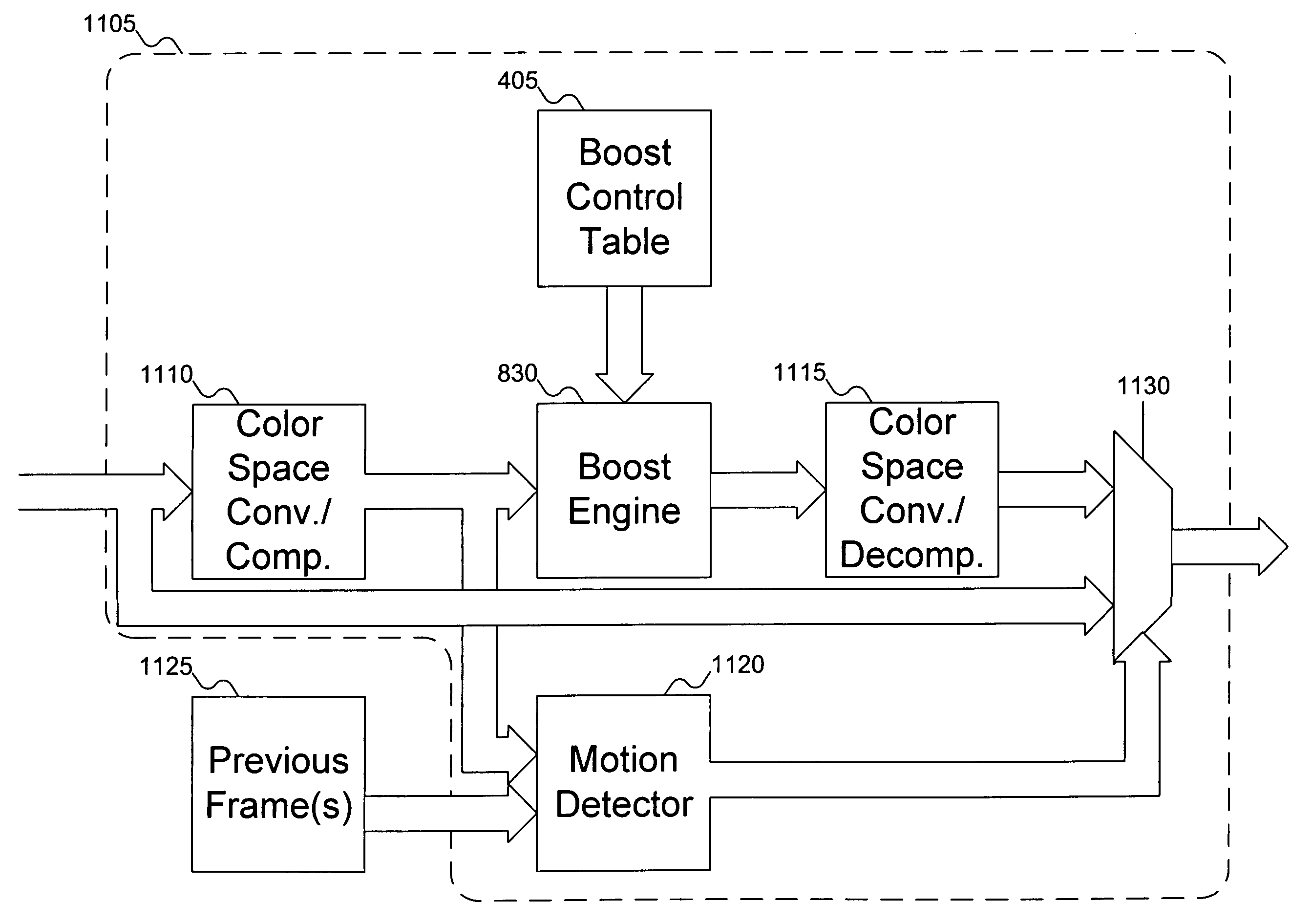
[0011]The invention includes a compressor to compress a pixel in an image frame. A motion detector detects motion by comparing the compressed pixel with the same pixel in one or more previous frames. If motion is detected, then th...

Problems solved by technology

The first disadvantage that most people think of is cost.
An LCD usually costs more than a comparably sized CRT monitor.
A second disadvantage of early model LCDs is their viewing angle.
If an LCD is viewed from outside its ordinary viewing angle, even if the screen is in a direct line of sight, the screen is essentially unreadable.
A third disadvantage is pixel responsiveness.
Because polarized filters block all light that is not at the correct angle, without the operation of the pixel, all light would be blocked.
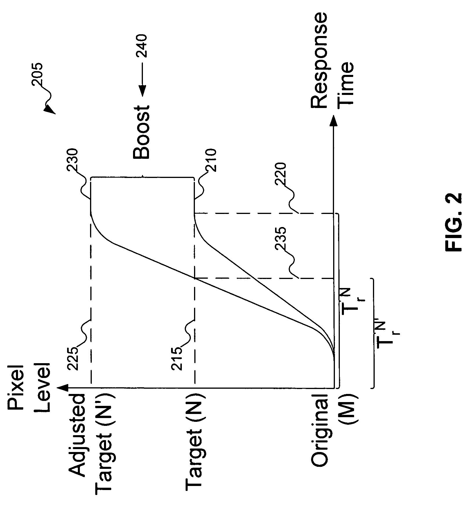
But there are limits to the responsiveness of any material used, and more advanced materials are also more expensive to manufacture.
But data compression typically results in some data loss (that is, the compression is lossy).

Method used


Image

  • Motion adaptive pixel boost with data compression and decompression
  • Motion adaptive pixel boost with data compression and decompression
  • Motion adaptive pixel boost with data compression and decompression

Examples


Embodiment Construction

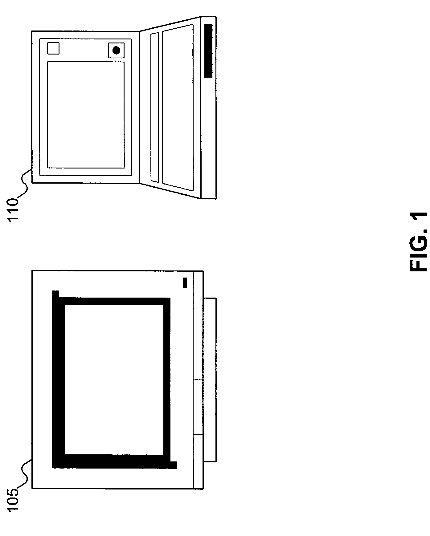
[0025]FIG. 1 shows devices to which embodiments of the invention can be adapted. FIG. 1 shows display 105 and laptop computer 110. Display 105 can be a computer monitor, or it can be a television display. Display 105 and laptop computer 110 are not necessarily connected; they are simply examples of devices that can benefit from the improved pixel response that is a consequence of the invention. Display 105 and laptop computer 110 (more specifically, the display built in to laptop computer 110) are typically devices using Liquid Crystal Display (LCD) displays, but a person skilled in the art will recognize that other devices that might benefit from embodiments of the invention. Examples of pixelated displays that might benefit from embodiments of the invention include active and passive LCD displays, plasma displays (PDP), field emissive displays (FED), electro-luminescent (EL) displays, micro-mirror technology displays, low temperature polysilicon (LTPS) displays, and the like for u...


PUM


Abstract

A compressed pixel level for a pixel in a frame of an image is compared with the (compressed) pixel level for the same pixel in a previous image frame. If the pixel level is unchanged, then the pixel is not moving. An uncompressed pixel level is then used for that pixel in the current image. If the pixel level is changed, then the pixel is moving, and a decompressed, boosted pixel level is used for that pixel in the current image.

Description

RELATED APPLICATION DATA[0001]This application is a continuation-in-part of commonly assigned co-pending U.S. patent application Ser. No. 10 / 931,312, titled “FUZZY LOGIC BASED LCD OVERDRIVE CONTROL METHOD”, filed Aug. 31, 2004, which is hereby incorporated by reference.FIELD OF THE INVENTION[0002]This invention pertains to liquid crystal displays, and more particularly to improving performance in liquid crystal displays.BACKGROUND OF THE INVENTION[0003]In the last few years, liquid crystal displays (LCDs) have jumped from being a small player to a dominant force in displays. First seen as monitors for computers, LCDs have advantages over cathode ray tube (CRT) displays. LCDs have a much smaller thickness, as they do not need the space or equipment to support the electron gun used in a CRT. This means that LCD displays could be used in places where a CRT was too bulky to fit neatly. The omission of the electron gun also lightened the display, meaning that an LCD is considerably light...

Claims


Application Information

Patent Timeline
IPC IPC(8): G09G5/02G09G3/36
CPCG09G3/3648G09G2320/0252G09G2340/16G09G2320/0285G09G2320/0261
Inventor ZHANG, HONGMINTANG, TIANHUA
Owner PIXELWORKS SEMICON TECH SHANGHAI CO LTD
Learn More