
Emergency telephone with integrated surveillance system connectivity

Inactive Publication Date: 2008-09-23
PR NEWSWIRE
View PDF146 Cites 49 Cited by
  • Summary
  • Abstract
  • Description
  • Claims
  • Application Information

AI Technical Summary

Benefits of technology

[0022]Various sensors and appliances may be combined with the emergency telephone system in this manner, greatly enhancing the response to the call while at the same time permitting response personnel to monitor the call for accuracy and authenticity.

Problems solved by technology

While these systems have been in wide use for many years, there remain several drawbacks to the usefulness of the system in dealing with many emergency situations.
There are many instances where a guard or other personnel is busy making rounds or with other duties and is not available to answer the call immediately upon transmission.
In certain types of situations, time may be a very critical factor in dealing with the emergency, and such delays in response can diminish the opportunity to deal with the emergency in the most effective manner.
Further, such systems do not permit the responding personnel to make any personal direct assessment of the emergency.
This presents a problem in determining whether the caller is overstating or understating the emergency conditions.
This problem is magnified by the fact that the caller may be under some stress when placing the call and may not be able to give accurate information in a calm manner, leaving it to the response personnel to make an assessment of the situation with less than optimum information.
In extreme cases, the person making the call may be injured or even incapacitated and not be able to make adequate disclosure of the emergency.
To date, emergency telephone systems have not been able to assure the quick and accurate responses that are available with the comprehensive, multimedia surveillance systems such as described in the aforementioned application.
An additional disadvantage is the reliance on landline telephone systems to transmit the call.

Method used


Image

  • Emergency telephone with integrated surveillance system connectivity
  • Emergency telephone with integrated surveillance system connectivity
  • Emergency telephone with integrated surveillance system connectivity

Examples


Embodiment Construction

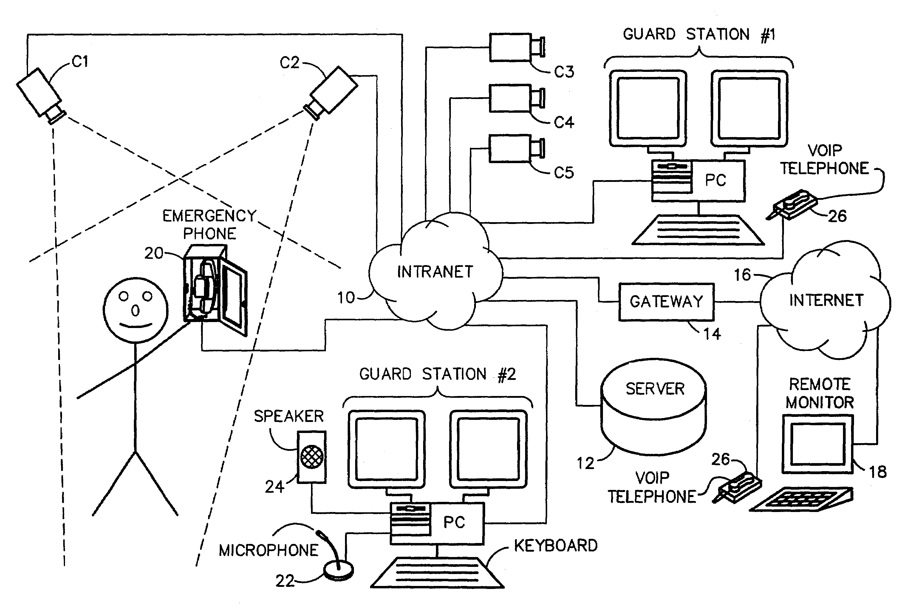
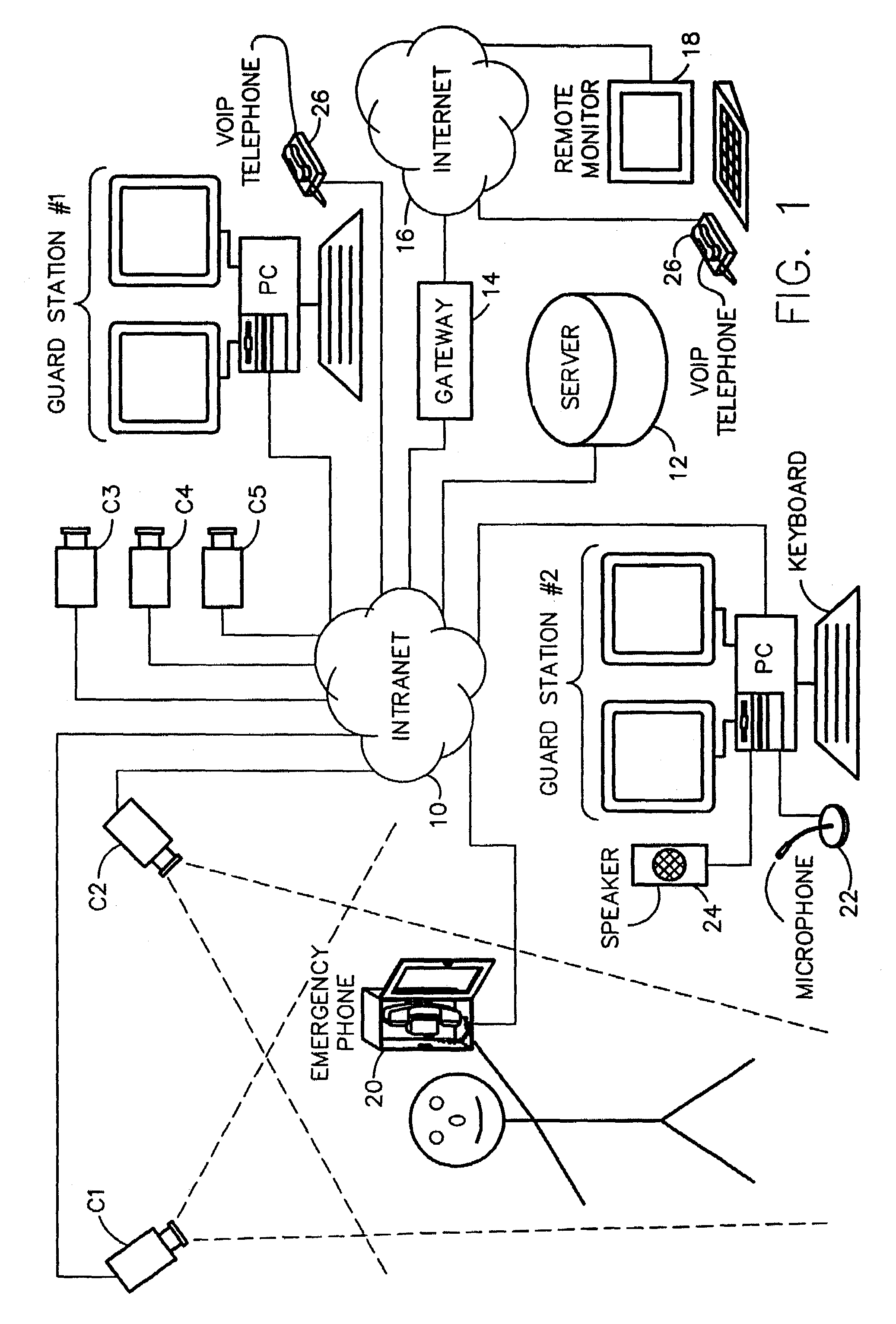
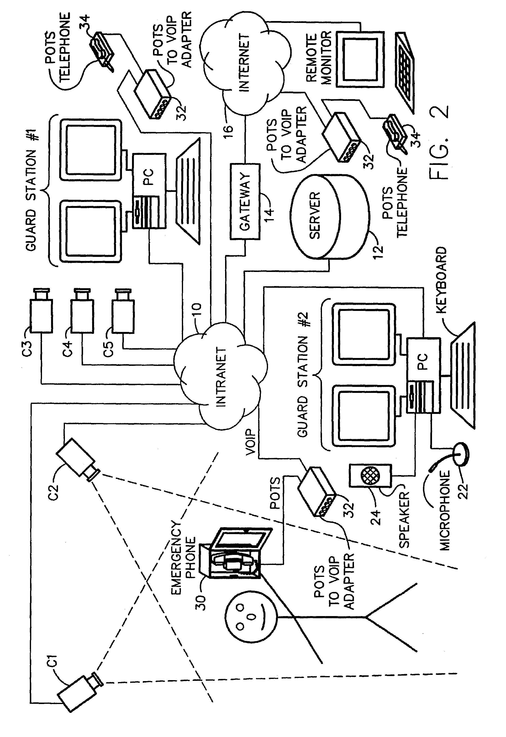
[0193]A typical surveillance system as more filly described in my aforementioned copending application is shown in FIG. 1 and includes, in this example, IP cameras C1, C2, C3, C4 and C5; a pair of manned guard station No. 1 and No. 2 on the intranet or LAN 10; a system server 12 also on the intranet 10; a gateway 14 to the Internet or other Wide Area Network (WAN) 16 and remote support such as the remote monitor station 18. An emergency IP voice telephone 20 is connected to the system via the intranet 10. In this embodiment, the emergency telephone sends IP protocol voice transmissions to the system via the intranet, where the system can capture the incoming call signal and transmit it to the various guard stations No. 1 and No. 2 and, via the Internet 16, to the remote station 18. This transmission can be done simultaneously or in a hierarchal order, as preferred and as managed by the server 12. In addition, once the incoming call is received, the location of the telephone 20 is id...


PUM


Abstract

A digital telephone or an analog telephone system with VOIP conversion is linked into the surveillance system and transmissions therefrom are treated as an event requiring an emergency response from the system. The system supports integration of emergency telephone systems into a multi-media surveillance system to permit comprehensive and multiple responses to an event triggered by receipt of the emergency phone call transmission. The telephone transmission is captured and transmitted to a surveillance system processor. Upon receipt, the system can react with any of numerous responses. First, the telephone call is transmitted to a manned station and may be answered in the normal fashion with a live voice response. The receipt of the call also activates the entire system in the same manner as a triggering signal from any other sensor or appliance. In addition, various other responses may be activated, either manually or in a pre-programmed hierarchy.

Description

BACKGROUND OF THE INVENTION[0001]1. Field of the Invention[0002]The subject invention is generally related to emergency telephone systems and is specifically directed to an emergency telephone system capable of being connected to and integrated with a network supported comprehensive multi-media surveillance system.[0003]2. Discussion of the Prior Art[0004]It is common practice to provide emergency telephones in strategic locations such as elevators, along highways and in various facilities such as airports, schools and hospitals. Typically these telephones are pre-programmed to dial a security or response station and automatically dial upon removal of the handset from the switch-hook or cradle. Most of these telephones are “Plain Old Telephone Service (POTS)” devices and are hard-wired to the landline telephone system and rely on a common carrier to transmit the call. In some cases, closed circuit systems or dedicated point-to-point systems sometimes called “ring-down circuits” may ...

Claims


Application Information

Patent Timeline
IPC IPC(8): H04N7/18G08B25/01G08B25/08H04N7/15
CPCG08B13/19634G08B13/19645G08B13/19656G08B13/19658G08B13/19671G08B25/005G08B13/19695G08B25/016G08B25/08H04N7/15H04N7/181G08B13/19684
Inventor MONROE, DAVID A.
Owner PR NEWSWIRE
Learn More