Piston ring with projection

a technology of piston rings and projection rings, applied in the field of piston rings, can solve the problems of reducing the effectiveness of piston rings and increasing the overall cost of piston rings, and achieve the effect of eliminating ring collapse and reducing the size of gaps

Active Publication Date: 2008-09-30
MAHLE ENGINE COMPONENTS USA
View PDF16 Cites 15 Cited by
  • Summary
  • Abstract
  • Description
  • Claims
  • Application Information

AI Technical Summary

Benefits of technology

[0011]The inventors of the present invention have recognized these and other problems associated with traditional piston rings described above. To this end, the inventors have developed a piston ring having a projection on an outer peripheral face thereby reducing the size of a gap between the outer peripheral face of the piston ring and a wall of a cylinder to eliminate ring collapse.

Problems solved by technology

However, twisting Napier-styled rings 10 has yielded other challenges for piston ring manufacturers.
As a result, ring collapse reduces the effectiveness of piston rings 10.
However, producing the bevel 28 requires a time-consuming and costly additional machining process, thereby increasing the overall cost of the piston ring 10.

Method used


Image

  • Piston ring with projection
  • Piston ring with projection
  • Piston ring with projection

Examples


Embodiment Construction

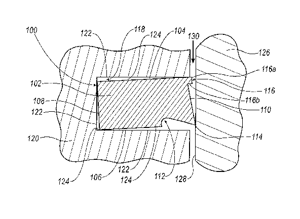
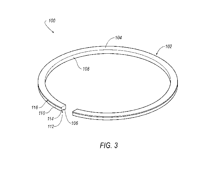
[0018]Referring now to FIGS. 3-5, a piston ring of the present invention is shown generally at 100. The piston ring 100 includes a generally annular body 102 having an upper surface 104, a lower surface 106, an inner peripheral face 108 and an outer peripheral face 110. The upper and lower surfaces 104, 106 are generally parallel and disposed between the inner and outer peripheral faces 108, 110.

[0019]Specifically, the lower surface 106 includes a generally hook-shaped groove 112 at the outer peripheral face 110 to define an edge 114. Further, the outer peripheral face 110 is generally tapered and extends outwardly from the upper surface 104 to the edge 114. In general, the piston ring 100 is commonly referred to in the art as a Napier-style or hook-groove piston ring.

[0020]However, unlike the conventional Napier-style piston ring, the outer peripheral face 110 of the piston ring 100 of the present invention further includes a projection 116. The projection 116 preferably extends ou...


PUM


Abstract

A piston ring is positioned in a groove of a piston and has an outer peripheral face. The outer peripheral face is generally tapered to an edge and includes a projection. The projection extends radially outwardly from the outer peripheral face along an upper surface of the piston ring. The projection reduces the gap between the outer peripheral face and a wall of the surrounding cylinder. The gap is typically exposed to combustion gases and the projection reduces the exposed area. Ring collapse is the separation of the outer peripheral face from the wall of the cylinder because of downward pressure forces of the combustion gases. Accordingly, the projection reduces the occurrence of ring collapse.

Description

FIELD OF THE INVENTION[0001]The present invention relates to a piston ring having generally parallel upper and lower surfaces with an outer peripheral face therebetween, and more particularly to a piston ring having an outer peripheral face including a radially extending projection to reduce a gap between the outer peripheral face of the piston ring and a surrounding cylinder wall.BACKGROUND OF THE INVENTION[0002]A piston reciprocates within a cylinder of an internal combustion engine and compresses fluids, such as gases, within a combustion chamber of the cylinder. These compressed fluids are then ignited to expand within the combustion chamber thereby forcing the piston away from the point of ignition and cycling the piston to its original position. Pistons typically include at least one groove for receiving a piston ring. The piston ring forms a seal with the wall of the cylinder to prevent gases from escaping from the combustion chamber.[0003]There are traditionally two differen...

Claims


Application Information

Patent Timeline
Patent Type & Authority Patents(United States)
IPC IPC(8): F16J9/00
CPCF16J9/206
Inventor CARSON, MICHAEL E.
Owner MAHLE ENGINE COMPONENTS USA
Why Eureka
Try Eureka