Dual directional coupler with multi-stepped forward and reverse coupling rods

a technology of forward and reverse coupling rods and directional couplers, which is applied in coupling devices, waveguide type devices, basic electric elements, etc., can solve the problems of design and manufacturability, all known directional couplers suffer from a number of disadvantages, and achieve high rf power handling, low dissipative loss, and extended frequency range

Active Publication Date: 2008-09-30
R&D MICROWAVES
View PDF8 Cites 21 Cited by
  • Summary
  • Abstract
  • Description
  • Claims
  • Application Information

AI Technical Summary

Benefits of technology

[0006]Although it is possible to design a dual directional coupler that would function somewhat similarly using a single quarter-wave section, the much more difficult design of a multi section, quarter-wave dual directional coupler is employed by the present invention. An advantage of the multi section design is wider bandwidth of operation can be realized as compared with single section design.
[0009]It is a further object of the present invention to provide a multi section airline coupler design where the coupling coefficient of different quarter wave sections is obtained by a reduction of the ground space distance in the area located away from the main line.
[0011]A further object of the present invention is to provide a dual directional coupler capable of having two couplers inside a common housing, so as to allow for independent measurements of forward and reverse power in one compact design.
[0012]It is yet another object of the present invention to provide a directional coupler, using airline coaxial transmission line structures, resulting in features such as extremely low dissipative loss and high RF power handling over an extended frequency range.
[0014]It is still a further object of the present invention to provide a directional coupler which is rugged, mechanically stable, and of a construction to make it applicable to both indoor and outdoor applications where high mechanical stresses and extreme weather conditions are present.
[0019]In some embodiments, the main conductor, the forward coupled conductor and the reverse coupled conductor each comprises a machined one-piece rod. In some embodiments, the first and second two section quarter wave directional couplers each comprises an asymmetric coupler. In certain of these embodiments, the dual directional coupler further includes terminations attached to each of the forward coupled conductor and the reverse coupled conductor in order to provide a good electrical match for the coupled conductors and good overall directivity of the coupler. In some embodiments, the dual directional coupler further includes dielectric strips disposed within the housing for enhancing directivity of the coupler.

Problems solved by technology

Although such directional couplers, including dual directional couplers, are known, for example, from U.S. Pat. Nos. 6,066,994, 6,573,807 and 6,600,307, all known directional couplers suffer from a number of disadvantages, particularly in their design and their manufacturability.

Method used


Image

  • Dual directional coupler with multi-stepped forward and reverse coupling rods
  • Dual directional coupler with multi-stepped forward and reverse coupling rods
  • Dual directional coupler with multi-stepped forward and reverse coupling rods

Examples


Embodiment Construction

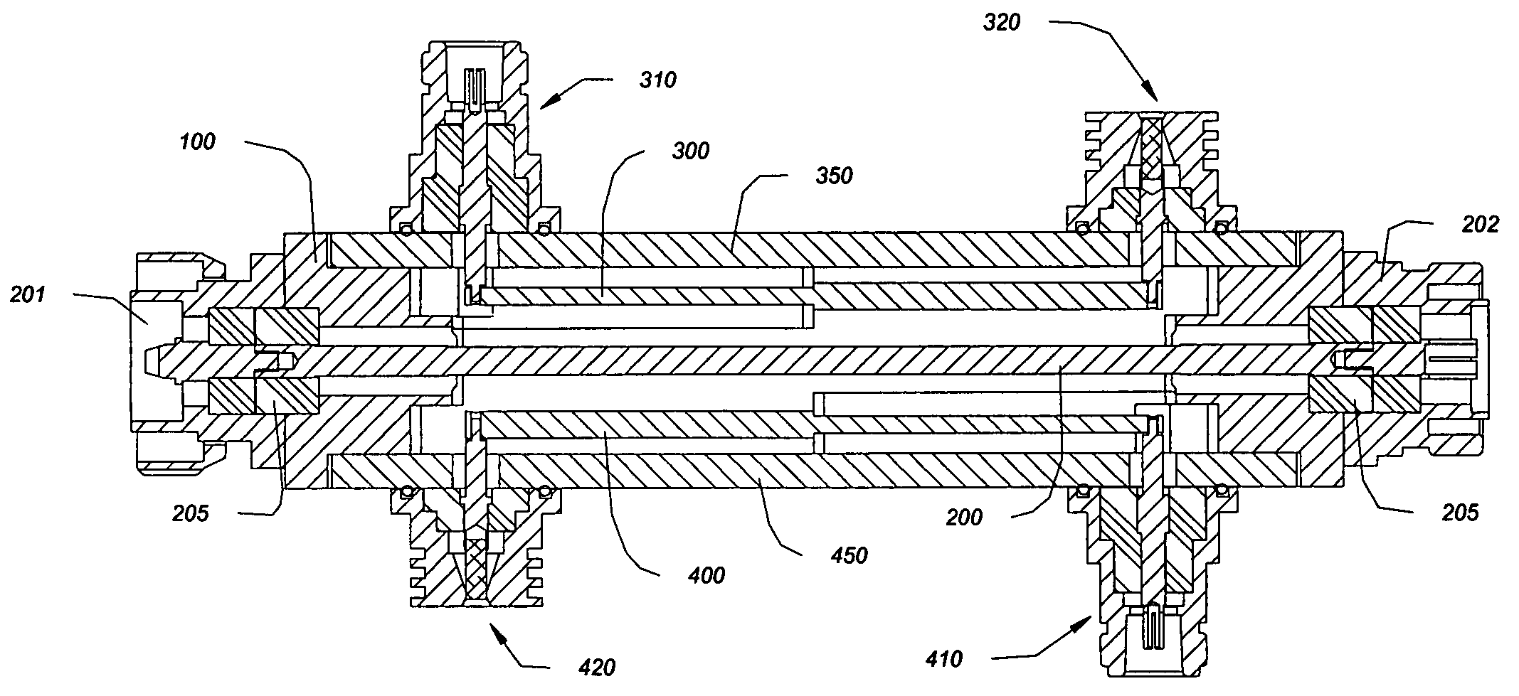
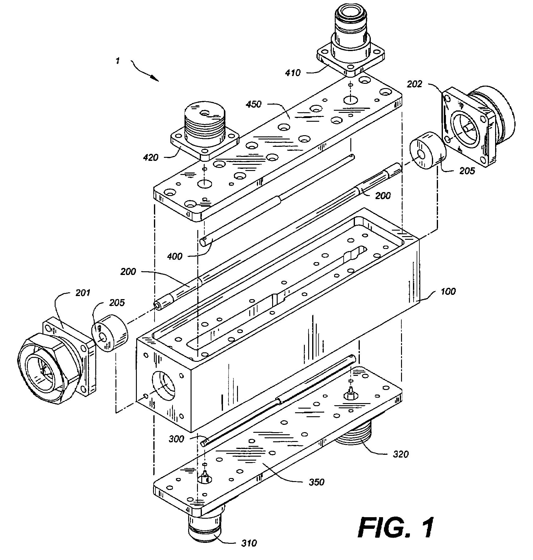
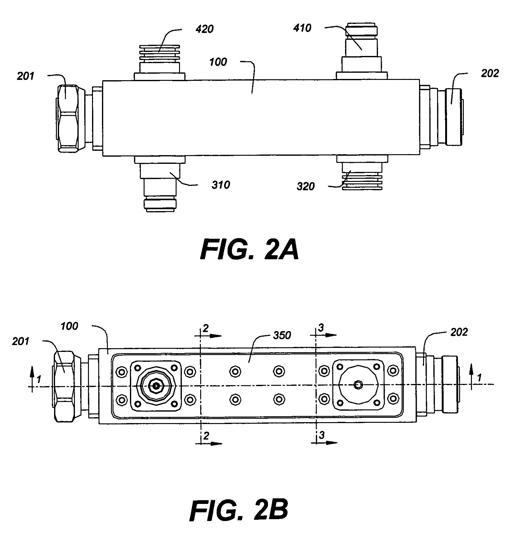
[0031]Referring first to FIGS. 1, 2A and 2B, a dual directional coupler (1) in accordance with the present invention is shown. As best shown in FIG. 1, the dual directional coupler (1) includes a housing (100), a main conductor (200), and a forward coupled conductor (300) as well as a reverse coupled conductor (400). The main line (200) along with the forward coupled conductor (300) form one, two section quarter wave coupler, while the same main line (200) and the reverse coupled line (400) form yet another two section directional coupler. The same main line (200) is shared by both couplers which allows for the compact design of this dual directional coupler (1). An alternate design would require two couplers positioned in series along the same main line, thus increasing the total length of the coupler by a factor of two.

[0032]The main conductor (200) is located centrally inside the housing (100) by means of the insulator supports (205), as shown in FIG. 1. The input connector (201)...


PUM


Abstract

A dual directional coupler includes a housing, a main conductor, a forward coupled conductor and a reverse coupled conductor. The main conductor, the forward coupled conductor and the reverse coupled conductor are arranged in parallel within the housing such that the main conductor and the forward coupled conductor define a first two section quarter wave directional coupler, and the main conductor and the reverse coupled conductor define a second two section quarter wave directional coupler.

Description

FIELD OF THE INVENTION[0001]The present invention relates generally to directional couplers, and more specifically to quarter wavelength dual directional couplers of improved design and manufacturability.BACKGROUND OF THE INVENTION[0002]A directional coupler has a through line through which a signal passes and at least one coupled line that samples the signal. At a basic level, a high-power directional coupler causes a sample of an electromagnetic wave propagating on the through line to propagate on the coupled line. Therefore, the coupled line serves to sample the signal on the through line. A directional coupler is capable of sampling signals propagating in two different directions. A signal flowing in a first direction on the through line is sampled on one port of the coupled line, while a signal flowing in the opposite direction is sampled on the other port of the coupled line.[0003]To measure output power or other high-power signals in a system, high-power handling capability i...

Claims


Application Information

Patent Timeline
Patent Type & Authority Patents(United States)
IPC IPC(8): H01P5/18
CPCH01P5/183
Inventor ANTKOWIAK, MAREK E.
Owner R&D MICROWAVES
Why Eureka
Try Eureka