Miniature bidirectional amplifier

a bidirectional amplifier and amplifier technology, applied in the field of bidirectional amplifiers, can solve the problems of increasing the collector charge and current gain of the rf components, affecting the service life of the amplifier, etc., and achieves the effect of sufficient heat dissipation capability and convenient installation and servi

Inactive Publication Date: 2008-09-30
HE SHIPING +3
View PDF14 Cites 21 Cited by
  • Summary
  • Abstract
  • Description
  • Claims
  • Application Information

AI Technical Summary

Benefits of technology

[0012]It is an aspect of the present invention to provide a small, lightweight amplifier device that is compatible with various 802.11 standards.
[0013]It is a further aspect of the invention to provide an amplifier casing that provides sufficient heat dissipating capabilities to ensure that the amplifier circuitry does not overheat when in operation.
[0014]It is a further aspect of the invention to provide an amplifier that is easy-to-install and service.
[0019]It is further desired to provide a bi-directional amplifier device that can receive and transmit RF signals compatible with one or more of the IEEE 802.11 standards, the amplifier device including an amplifier circuit and an enclosure device operable to house the amplifier circuit, wherein heat generated by the amplifier circuit when in operation is sufficiently dissipated through an outer cylindrical surface of said enclosure device such that no additional heat dissipation devices are required to ensure proper operation of the amplifier circuit.

Problems solved by technology

However, conventional amplifiers typically comprise large bulky enclosures with big metal fins used for dissipating heat generated by the amplifier circuits.
If the heat generated by the amplifier circuit is not dissipated properly by the casing of the amplifier circuit, the temperature will rise so high that some, if not all, of the electrical components comprising the amplifier will burn out and become inoperable.
Further, high temperatures within the amplifier increase the collector charge and current gain of the RF components.
High collector charge and current gain will decrease the performance of these components and force the equipment to malfunction.
This type of heatsink limits the mobility of the amplifier and, hence, the applications in which it can be used.
Additionally, conventional amplifiers are large and bulky and often do not provide provisions against lightning strikes.
If lightning strikes the amplifier, either directly or indirectly, and the device does not have provisions for dissipating the electricity, the results are typically fatal for the amplifier and, potentially, other equipment downstream from the amplifier.
The addition of the lightning arresting device separate from the amplifier not only increases the overall expense, but it also increases the installation time necessary to install the system.

Method used


Image

  • Miniature bidirectional amplifier
  • Miniature bidirectional amplifier
  • Miniature bidirectional amplifier

Examples


Embodiment Construction

[0035]Exemplary, non-limiting, embodiments of the present invention are discussed in detail below. While specific configurations and dimensions are discussed to provide a clear understanding, it should be understood that the disclosed dimensions and configurations are provided for illustration purposes only. A person skilled in the relevant art will recognize that other dimensions and configurations may be used without departing from the spirit and scope of the invention.

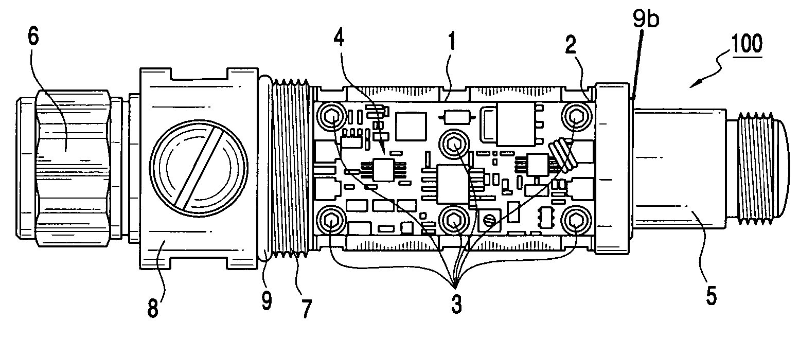
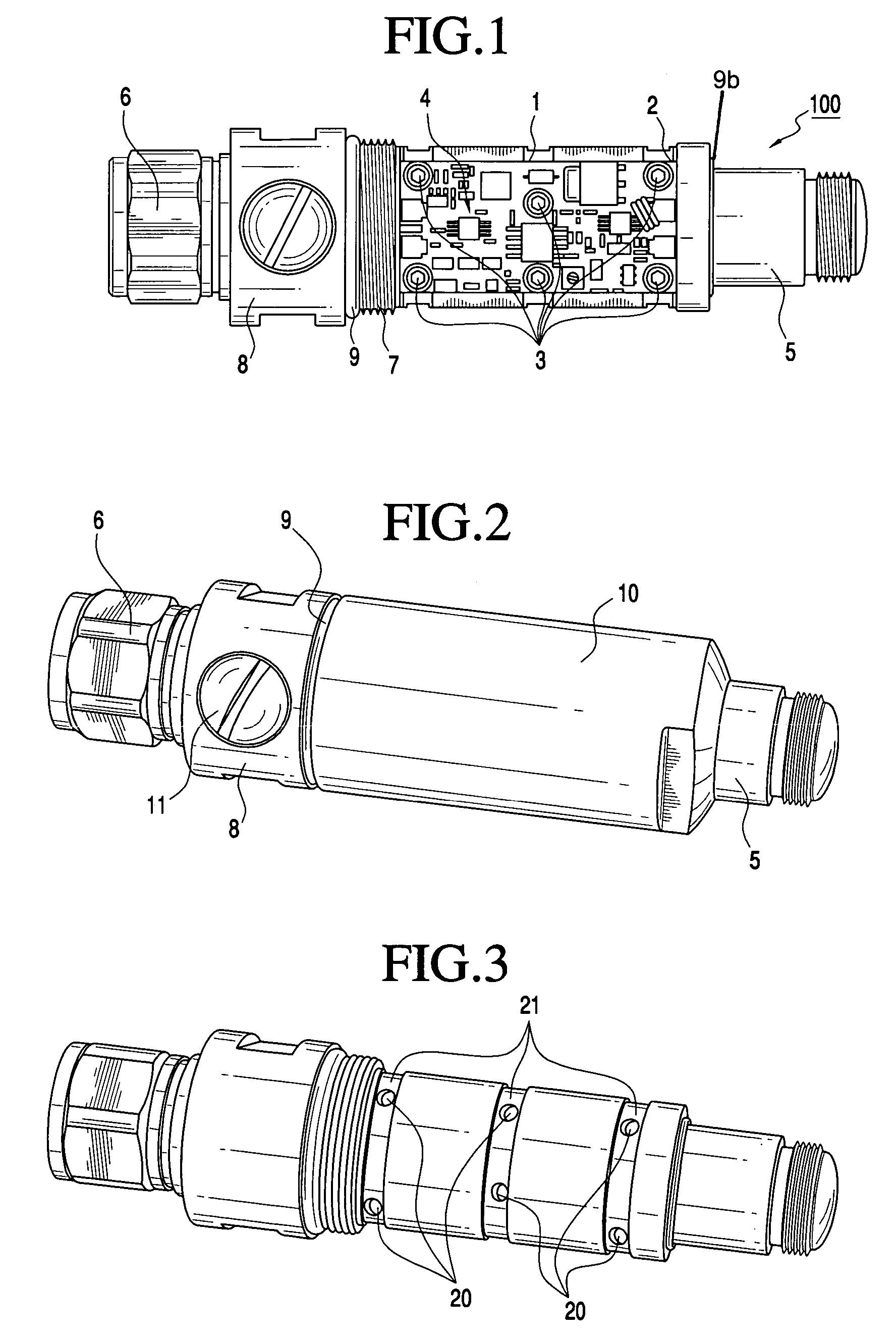
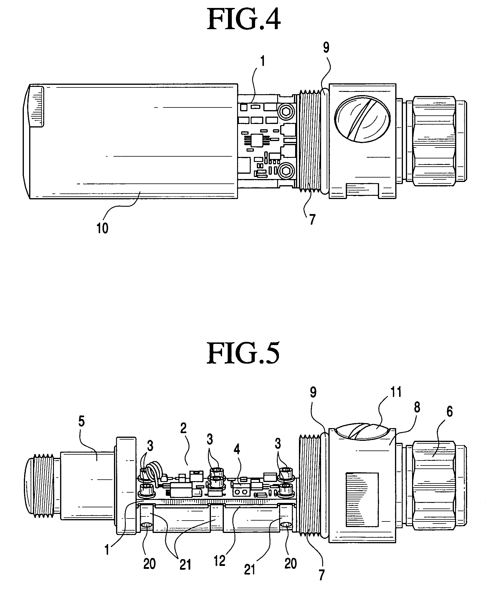
[0036]FIG. 1 illustrates an amplifier device 100 in accordance with one embodiment of the present invention. As shown in FIG. 1, amplifier 100 includes a printed circuit board (PCB) 1 mounted to a substantially flat part of a mounting portion 2 of a metal enclosure device. The PCB 1 is mounted to the metal enclosure device in the present embodiment using metal screws 3; however, a skilled artisan would understand that other mounting techniques are also suitable. For example, epoxy, rivets, and mating releasably inte...


PUM


Abstract

An amplifier device for amplifying RF communication signals compatible with IEEE 802.11 standards. An amplifier circuit is housed within a cylindrical metal housing that provides excellent heat dissipation and requires no mounting hardware for installing the device within a communication system. The metal housing with an integrated lightning arrestor creates a watertight seal to protect the amplifier circuit from damage when installed outdoors and the amplifier circuit is compatible with both 2.4 GHz and 5.8 GHz frequency applications.

Description

CROSS REFERENCE TO RELATED APPLICATIONS[0001]This application is an application filed under 35 U.S.C. § 111(a) claiming benefit pursuant to 35 U.S.C. § 119(e)(1) of two Provisional Applications, Ser. No. 60 / 566,595 filed on Apr. 30, 2004 and Ser. No. 60 / 664,546 filed Mar. 24, 2005, which were filed pursuant to 35 U.S.C. § 111(b), the entire contents of which are incorporated herein by reference.FIELD OF THE INVENTION[0002]This invention relates generally to a bi-directional amplifier used for wireless communications. More particularly, the invention relates to a miniature bi-directional amplifier housed in a specially-shaped, rugged, water-proof housing that permits ease of handling and outdoor use and also provides heat-dissipation for circuitry housed within.BACKGROUND OF THE INVENTION[0003]Before providing specific background information in regard to the specific invention disclosed below, a brief general background is provided along with a few definitions for terms relevant to t...

Claims


Application Information

Patent Timeline
Patent Type & Authority Patents(United States)
IPC IPC(8): H04M1/00H03F3/24H03F3/60H03F3/62H03F3/72H04B1/38
CPCH03F3/24H03F3/604H03F3/62H04B1/3877H03F3/72H03F2200/111H03F2200/423H03F2203/7209
Inventor HE, SHIPINGHANG, JIEGE, DAVIDJAMAL, MOHAMMED N.
Owner HE SHIPING
Why Eureka
Try Eureka