Heat conducting lamp base and LED lamp including the same

a technology of led lamps and heat conducting lamps, which is applied in the field of led lamps, can solve the problems of shortened life, high light fade, and large amount of heat produced by led lamps in operation, and achieve the effects of reducing the size of the lamp

Inactive Publication Date: 2013-09-19
MASS TECH (HK) LTD
View PDF5 Cites 1 Cited by
  • Summary
  • Abstract
  • Description
  • Claims
  • Application Information

AI Technical Summary

Benefits of technology

[0009]The purpose of the present invention is to overcome the disadvantages of the prior art by providing a heat conducting lamp base, through which the heat generated during the luminescence of the LED light source can be effectively dissipated out by various means. As no heat dissipating device or structure needs to be arranged in the main part of the lamp, the size of the lamp can be reduced and the structure of the lamp can be simplified, while effective heat dissipation can be obtained.

Problems solved by technology

However, LEDs would produce a large amount of heat in operation.
If this heat is not promptly dissipated, the performance of the LEDs will be affected, resulting in high light fades and shortened life span.
Because the problem of the heat dissipation remains with the HPLEDs, replaceable LED light sources with high power have not yet been developed, while one piece (irreplaceable) LED lamps presently have a power up to around 100 Watts.
In addition, the LED reflector lamp may have no lampshade at the opening of the reflector cup, allowing the LED light source to communicate directly with air so as to facilitate the heat dissipation, which further reduces the heat energy when the LED is luminous.
It is undesirable that such an arrangement cannot effectively solve the heat dissipation problem of the HPLED lamps, because it is impossible for the heat dissipating devices or structures to indefinitely increase their heat dissipating area to cater for the heat generation of HPLEDs, if they are provided in the body of the lamps.
Notably, the prior art heat dissipating devices lack the ability to adapt for the LEDs with a power of hundreds of Watts and even thousands of Watts.

Method used


Image

  • Heat conducting lamp base and LED lamp including the same
  • Heat conducting lamp base and LED lamp including the same
  • Heat conducting lamp base and LED lamp including the same

Examples


third embodiment

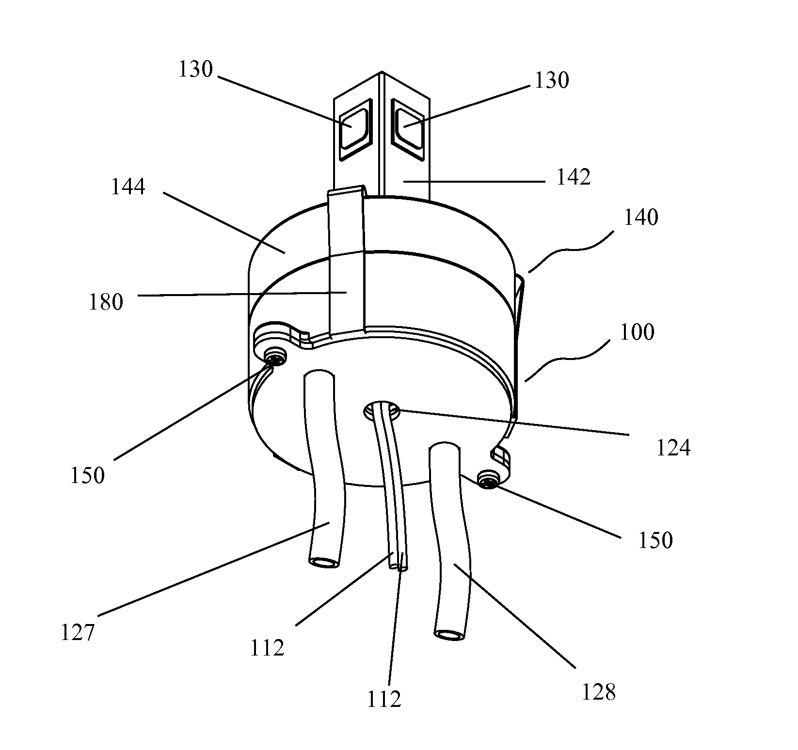
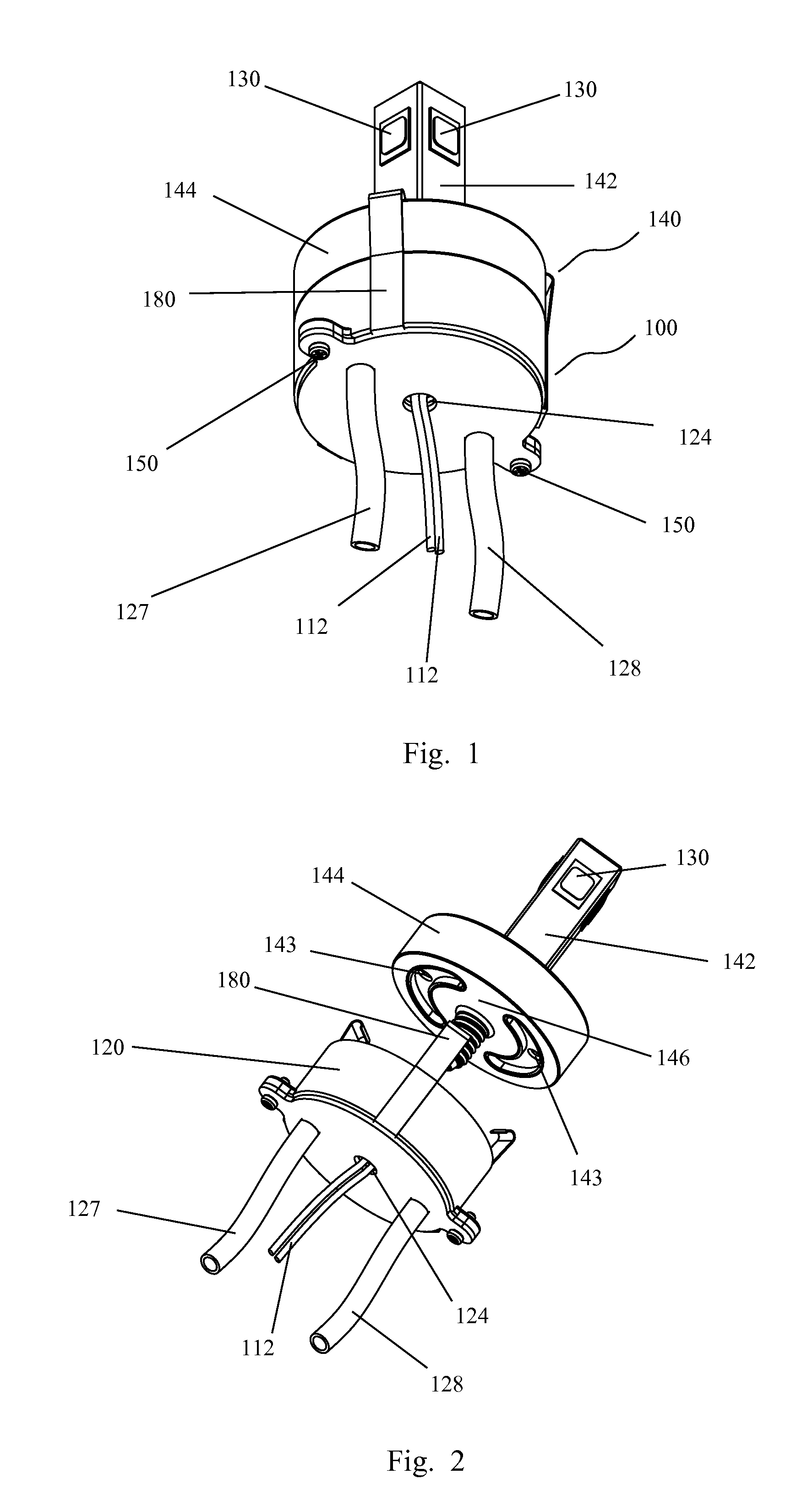
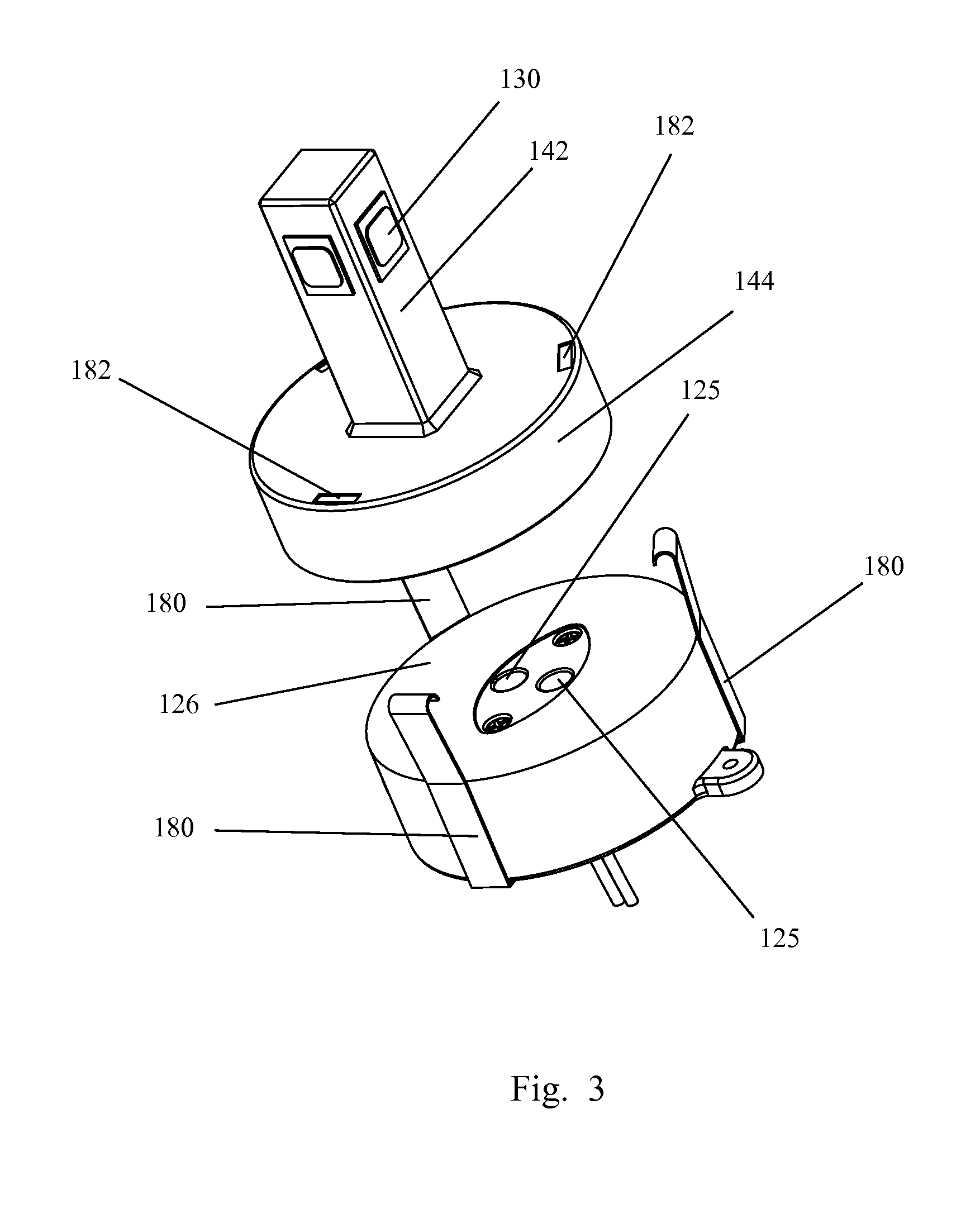
[0049]FIGS. 10 and 11 illustrate a heat conducting lamp base according to the present invention. In this embodiment, the heat conducting portion 120 is in the shape of cuboid, and the lower part 144 of the heat conducting member 140 of the LED light source is correspondingly cuboidal. The heat conducting portion 120 and the lower part 144 are clamped tightly together by snap-fitting the clamps 180 provided on the two ends of the heat conducting lamp base 100 into bulges formed on the two ends of the lower part 144, in order to maintain a good heat conduction. Two electric pins 149 of the LED light source extend from the bottom surface of the lower part 144 of the heat conducting member 140, forming electrical connection with the power socket 110 on the lamp base and creating a closed loop with the power lines 112. As can be seen in FIG. 10, the cooling medium inlet and the cooling medium outlet are respectively provided on the two end surfaces of the cubodial heat conducting portion...

first embodiment

[0051]The other structures and functions of this embodiment are basically identical to those of the first embodiment described above.

[0052]FIG. 12 illustrates a specific LED lamp comprising the heat conducting lamp base according to the present invention, wherein the LED lamp is a car headlight. As illustrated in the figure, the heat generated when the car headlight is turned on is transferred to the heat conducting portion of the heat conducting lamp base, and then transferred to the cooling medium inside the cooling medium piping through heat conduction. Subsequently, the cooling medium returns to an external heat exchanger 320. As known to a person skilled in the art, the car has its own radiator 400 comprising a cooling water tank, the water in which is further cooled down by a fan 410. The cold source of the heat exchanger 320 of the car headlight is provided by the cooling water used in the radiator 400 of the car.

[0053]FIG. 13 illustrates another specific LED lamp comprising ...


PUM


Abstract

A heat conducting lamp base (100) includes a heat conducting portion (120) and a power socket (110) electrically connected to a LED light source (130). The heat conducting portion (120) is made of a thermally conductive material and has at least one heat conducting surface (126). The heat conducting surface (126) is contacted with a heat conducting member (140) of the LED light source (130) so as to facilitate the heat conduction. The heat conducting portion (120) is coupled to at least one part of the power socket (110) and to a heat sink (300) to allow dissipation of heat generated by the LED light source (130). A LED lamp comprising the heat conducting lamp base is provided. The heat conducting lamp base solves the heat dissipation problem of high power LEDs and permits the lamps of small size.

Description

TECHNICAL FIELD[0001]The present invention relates to the field of illuminating lamps. More specifically, the present invention relates to a lamp base capable of heat conduction and a light-emitting diode (LED) illuminating lamp comprising the heat conducting lamp base.BACKGROUND OF THE INVENTION[0002]As a solid state light source with huge development potentials, LEDs (light-emitting diodes) emerged in the sixties of the 20th century and have attracted increasing attention for their advantages such as long life span, safety, environmental friendliness, small size, light weight and low power consumption such that they are becoming to take the place of traditional high pressure halogen lamps in a wide range of lighting applications. The emergence of high-power LEDs (HPLEDs) accelerates the replacement of traditional illuminative light sources by the LEDs and makes it possible to apply LED lamps in scenarios where high-power illumination is required.[0003]HPLEDs, such as illuminating ...

Claims


Application Information

Patent Timeline
Patent Type & Authority Applications(United States)
IPC IPC(8): F21V29/00F21V29/02
CPCF21K9/30F21V29/30F21Y2101/02F21S48/323F21V29/02F21V29/70F21V19/001F21S48/325F21S48/326F21V29/58F21V29/22F21V23/06F21V29/60F21V29/83F21V29/85F21V29/86F21V29/89F21Y2115/10F21S45/43F21S45/465F21S45/48F21S45/49
Inventor FOO, ONN-FAH
Owner MASS TECH (HK) LTD
Why Eureka
Try Eureka