Master cylinder and method of mounting stopper plate

a stopper plate and master cylinder technology, applied in the direction of rotary clutches, braking systems, fluid couplings, etc., can solve the problems of high parts and machining costs, damage to the cup, and out of the cup, so as to reduce the backward movement of the secondary piston, increase the thickness of the stopper plate, and ensure the effect of stopping the backward movemen

Inactive Publication Date: 2008-10-07
ADVICS CO LTD
View PDF8 Cites 2 Cited by
  • Summary
  • Abstract
  • Description
  • Claims
  • Application Information

AI Technical Summary

Benefits of technology

[0010]An object of the present invention is to provide an arrangement for restricting the backward movement of the secondary piston of a tandem master cylinder when hydraulic fluid is rapidly returned into the second pressure chamber during e.g. traction control which comprises a small number of parts and can be assembled with a small number of steps.
[0012]Thus, the arrangement for restricting the backward movement of the secondary piston according to the present invention comprises the groove and only one additional component (stopper plate), so that it can be assembled easily with a smaller number of steps and at a low cost.
[0015]With this arrangement, since the stopper plate can be inserted into the cylinder bore with one of the flanges of the stopper plate located ahead of the other, it is not necessary to radially expand the flanges to bring the flanges into engagement with the shoulder. This makes it possible to increase the thickness of the stopper plate to ensure sufficient strength of the stopper plate so that it can withstand the force applied thereto from the secondary piston when the secondary piston moves backward under high pressure. Thus, the stopper plate according to the invention can reliably restrict the backward movement of the secondary piston.

Problems solved by technology

If the pistons are unduly pushed back as a result, they may come out of the cups.
Once the pistons come out of the cups, they may damage the cups when returning to their inoperative positions.
The cost of the parts and the machining cost are therefore high.
It is difficult to insert the retainer into the cylinder bore from its open end.
Thus, the thickness of the extension of the retainer is limited and so is the strength of the flange.
This makes it difficult to reliably restrict the backward movement of the flange.

Method used


Image

  • Master cylinder and method of mounting stopper plate
  • Master cylinder and method of mounting stopper plate
  • Master cylinder and method of mounting stopper plate

Examples


Embodiment Construction

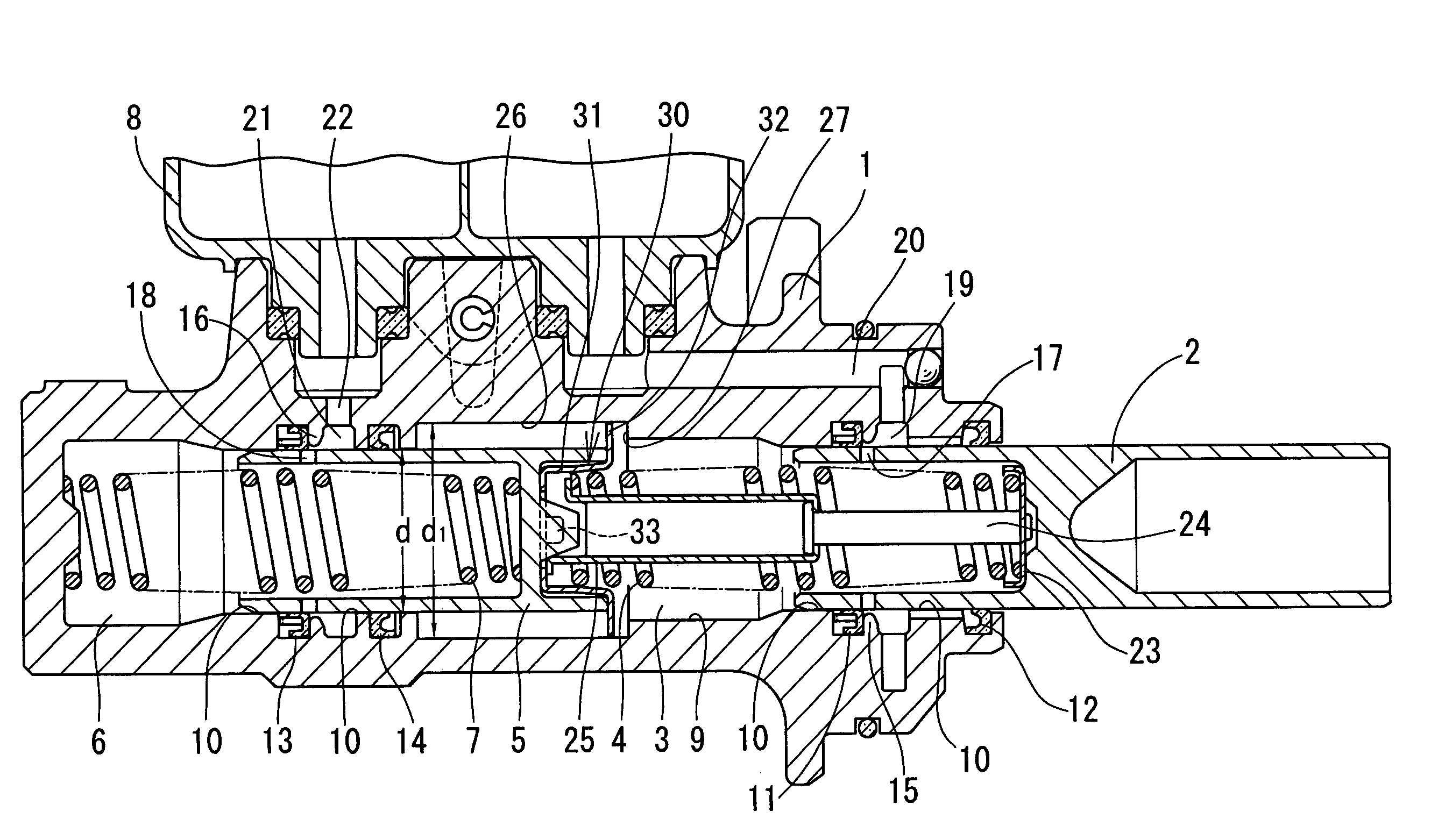
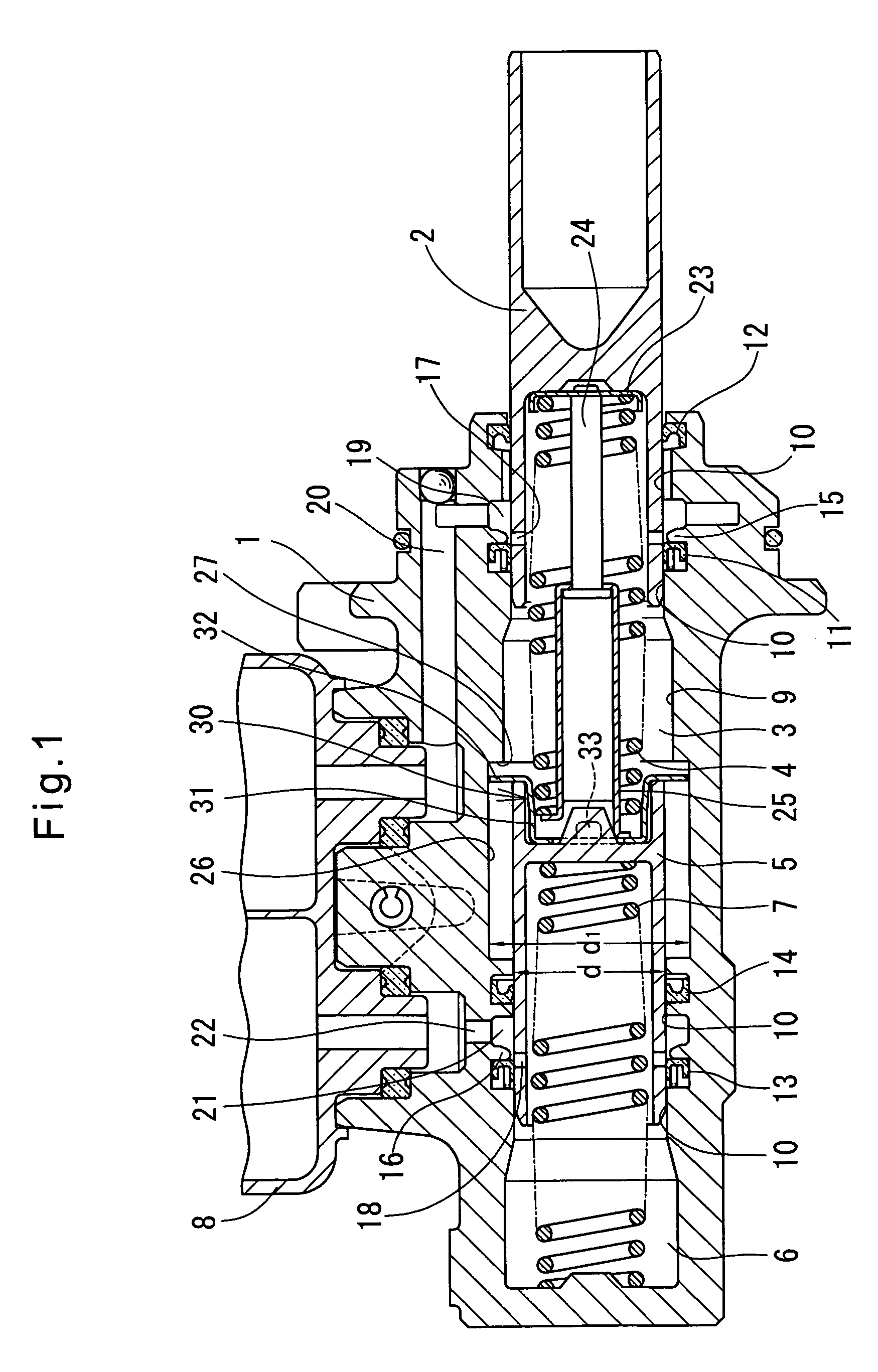
[0021]The master cylinder embodying the present invention is now described with reference to FIGS. 1 to 4. As shown in FIG. 1, the master cylinder comprises a cylinder body 1, a primary piston 2 received in the cylinder body 1, a return spring 4 for the primary piston 2, a secondary piston 5 mounted in the cylinder body 1 forwardly (leftwardly in FIG. 1) of the primary piston 2, a return spring 7 for the secondary piston 5, and a reservoir 8. The primary piston 2 and the secondary piston 5 define a first pressure chamber 3 therebetween in which brake hydraulic pressure is produced by pressurizing the hydraulic pressure therein with the primary piston 2. Between the secondary piston 5 and the end wall of the cylinder body 1, a second pressure chamber 6 is defined in which brake hydraulic pressure is produced by pressurizing the hydraulic fluid therein with the secondary piston 5. The primary piston 2 and the secondary piston 5 are slidable along sliding surfaces 10 of a cylinder bore...


PUM


Abstract

A master cylinder includes primary and secondary pistons both slidably mounted in the cylinder bore of a cylinder. A stopper plate is disposed in the cylinder bore behind the secondary piston. A groove having a larger diameter than the piston sliding surfaces is formed in the inner wall of the cylinder bore at its axially intermediate portion. The stopper plate includes a pair of diametrically opposed flanges having an outer diameter larger than the diameter of the piston sliding surfaces and smaller than the diameter of the groove. The flanges are received in the groove and engageable with a shoulder formed at the rear end of the groove, thereby preventing excessive backward movement of the secondary piston. The stopper plate has a dimension perpendicular to the direction in which the flanges extend and smaller than the diameter of the piston sliding surfaces. Thus, the stopper plate can be inserted into the cylinder bore with one of the flanges located ahead of the other.

Description

CROSS REFERENCE TO RELATED APPLICATIONS[0001]This application is based on and claims priority under 35 U.S.C. sctn. 119 with respect to Japanese Patent Application No. 2005-196339 filed on Jul. 5, 2005, the entire content of which is incorporated herein by reference.BACKGROUND OF THE INVENTION[0002]The present invention relates to a master cylinder for a vehicle hydraulic brake system, and a method of mounting a stopper plate for preventing excessive backward movement of a secondary piston of the master cylinder.[0003]Many of today's vehicle hydraulic brake systems have an automatic brake function such as traction control (TRC) or electronic stability control (ESC).[0004]In a vehicle hydraulic brake system having an automatic brake function, during e.g. TRC, hydraulic fluid is supplied from a hydraulic pressure source including a power pump toward selected wheel cylinders. During such automatic brake control, hydraulic oil often returns suddenly and rapidly into pressure chambers in...

Claims


Application Information

Patent Timeline
Patent Type & Authority Patents(United States)
IPC IPC(8): B60T11/20B60T11/28
CPCB60T11/20
Inventor GOTO, YUJI
Owner ADVICS CO LTD
Why Eureka
Try Eureka