Adjustable focus connector with spring action

a technology of focus connector and spring action, which is applied in the field of connectors, can solve the problems of reducing the effectiveness of precision capture and transfer of light in optical delivery systems, reducing the efficiency of existing connectors for optical fibers, and high cost of stages, so as to achieve efficient coupling, optimize coupling, and ensure the effect of positioning

Active Publication Date: 2008-10-07
OZ OPTICS
View PDF5 Cites 15 Cited by
  • Summary
  • Abstract
  • Description
  • Claims
  • Application Information

AI Technical Summary

Benefits of technology

[0016]3) A spring-loaded mechanism to prevent accidental jamming of the fiber;
[0020]The connector of the present invention is very useful in achieving efficient coupling with a laser to fiber coupling system such as that discussed above with reference to U.S. Pat. Nos. 4,753,510 and 4,889,406, permitting for precise adjustment of the focus. It is also very useful in fiber-to-fiber coupling systems using two collimators facing each other. As long as at least one side utilizes the connector of the present invention it is possible to achieve precise positioning in X, Y and Z planes as well as with respect to pitch and yaw, optimizing coupling and minimizing losses. The possibility of avoiding contact between fiber ends also permits the coupler to be used in high power situations where contact between fiber ends can lead to damage of the fibers. In straight fiber-to-fiber coupling systems the spring loading achievable with the invention allows the ferrule ends to mate without damage, while the adjustment feature of the invention allows for the deliberate introduction of a gap between the fiber ends, such that the coupler can function as an attenuator.

Problems solved by technology

Existing connectors for optical fibers suffer from several limitations that reduce their effectiveness for precision capture and transfer of light in optical delivery systems, particularly high power laser systems.
Such stages are expensive, and are not applicable to systems where the fiber must be aligned, and semi-permanently attached.
The limitation of this technique is that if the laser beam is not well collimated the focused spot will not lie at the focal plane of the lens, and thus it will not lie at the tip of the fiber.
First the lens is between the fiber and the laser, and is often thus inaccessible.
The other is that moving the lens along the Z axis usually causes unwanted motion (play) in the other planes, particularly X and Y.
This has the drawback of being unable to control the roll of the fiber, making it unusable for polarization maintaining fiber applications.
Another issue that one wants to avoid is accidentally extending a fiber too close to a lens or other surface, possibly jamming and damaging the tip of the fiber.
However, in these patents the spring action is not such as to permit any compressive movement after the connector Z-position is located.
This leaves open the possibility of jamming and damage to the ferrule tip should it be mated to conventional connectors or receptacles, which rely on some compressive spring action being present when mating.

Method used


Image

  • Adjustable focus connector with spring action
  • Adjustable focus connector with spring action
  • Adjustable focus connector with spring action

Examples


Embodiment Construction

FCC Type Fiber Optic Connector

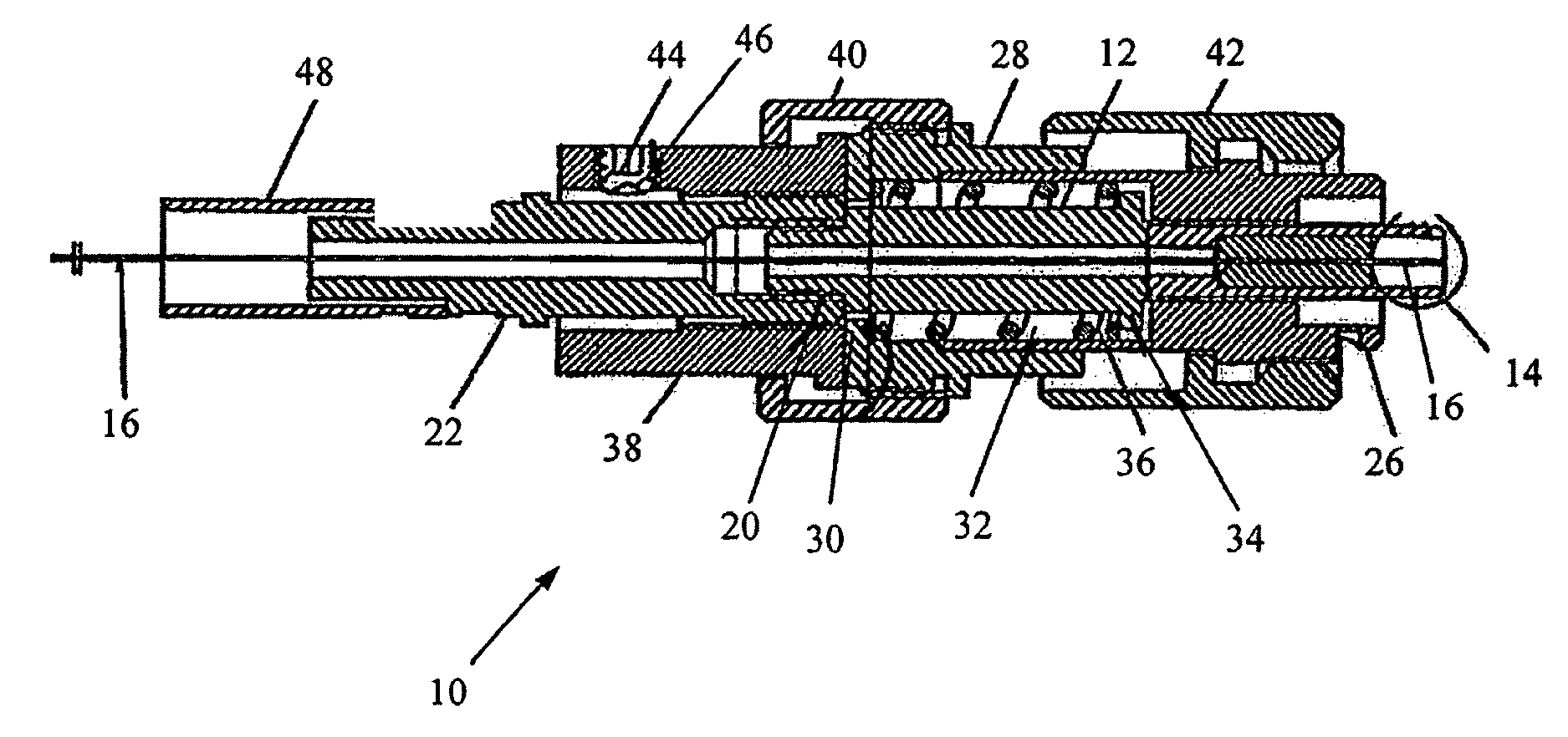
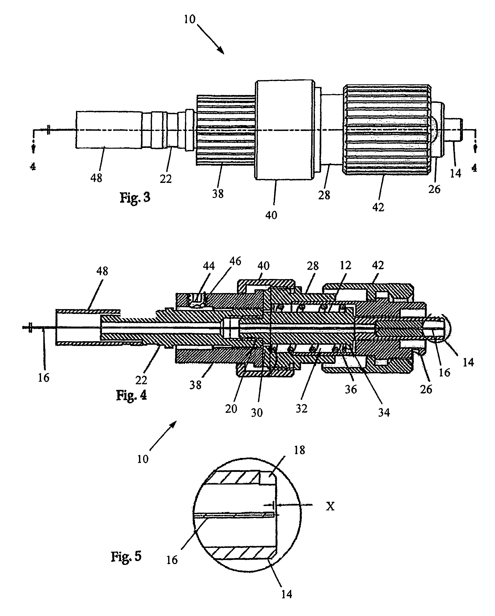
[0035]FIGS. 3 to 6 illustrate an adjustable fiber optic connector 10 according to the present invention especially adapted for use with an FCC type of connector or receptacle.

[0036]A ferrule holder 12 presents a counterbore in a distal end section thereof (right hand side in FIG. 4) for the mounting of any type of FCC ferrule 14. The ferrule (high power version shown) may be of any type suitable to the end user's purpose.

[0037]The high power ferrule concept is presented here as it is often seen in use with adjustable focus connector. Note that the fiber 16 is suspended in free space with a protective ring around it to prevent accidental damage to the exposed fiber. This design has two features that are advantageous. With reference to FIG. 5 it is first of all seen that the fiber tip is recessed by a distance x, only a few microns, preventing any damage to the fiber should the tip come in contact with a flat surface. The second is the presence of a notch...


PUM


Abstract

An adjustable focus connector with spring action is especially adapted for use with common FC or SAM fiber optic receptacles. The connector includes a ferrule holder which mounts a fiber-carrying ferrule at a distal end thereof. At its proximal end the ferrule holder is threadedly connected to a lead screw member. A thrust collar surrounds the ferrule holder and traps a compression spring in the cavity between the thrust collar and the ferrule holder. Because of appropriate interengagement between the components the ferrule holder cannot rotate relative to the trust collar. A traveler is threadedly connected to the lead screw and abuts against the thrust collar. A connection nut is provided at the distal end of the connector to connect it to the fiber optic receptacle. The spring action of the connector prevents damage to the fiber end during connection of the connector to the fiber optic receptacle.

Description

CROSS-REFERENCE TO RELATED APPLICATION[0001]This application claims the benefit of Provisional U.S. Patent Application Ser. No. 60 / 760,406 filed Jan. 20, 2006.FIELD OF THE INVENTION[0002]The present invention relates to connectors for connecting optical fibers to receptacles therefore and other related equipment.BACKGROUND OF THE INVENTION[0003]Existing connectors for optical fibers suffer from several limitations that reduce their effectiveness for precision capture and transfer of light in optical delivery systems, particularly high power laser systems. Fundamental to any such system is the ability to precisely position the fiber at the focus of a laser beam in free space (X, Y and Z planes.).[0004]Prior Art FIG. 1 defines the initial application of focusing light into a fiber. A focusing objective lens 100 focuses the light from a laser to a spot 102 closely matching the diameter of the core 104 of fiber 106. This can be as small as 2 to 3 microns in diameter. The fiber then has ...

Claims


Application Information

Patent Timeline
Patent Type & Authority Patents(United States)
IPC IPC(8): G02B6/36
CPCG02B6/3821G02B6/4296G02B6/266G02B6/3506G02B6/3552G02B6/3594G02B6/4292
Inventor SEZERMAN, OMUR M.BEST, GARLANDNGUYEN, THOBAKEELER, STEVEN
Owner OZ OPTICS
Why Eureka
Try Eureka