
Laser beam hardening tool

a technology of laser beam and tool, which is applied in the field of laser beam hardening tools, can solve the problem that the structure of the machine tool has not been proposed

Active Publication Date: 2008-10-07
YAMAZAKI MAZAK KK
View PDF27 Cites 8 Cited by
  • Summary
  • Abstract
  • Description
  • Claims
  • Application Information

AI Technical Summary

Benefits of technology

[0011]According to this aspect of the invention, it is possible to avoid the interruption between the optical path for supplying the beam guide path with laser beam (beam guiding portion) and the tool holding portion.
[0013]According to this aspect of the invention, the optical position of laser beam can be easily adjusted only by changing the position of the beam guiding body.
[0015]According to this aspect of the invention, the accuracy of the position of the beam guide path can be enhanced.
[0017]According to this aspect of the invention, attachment of foreign objects to the end portion of the beam guide path can be restricted, thereby avoiding power down of laser beam due to the presence of foreign objects in the beam guide path.
[0019]According to this aspect of the invention, the shutter member can be freely moved according to installation / detachment of the laser beam hardening tool, so that an operation for moving the member is not necessary, thereby avoiding an error operation and never failing to operate.

Problems solved by technology

Both mechanical machining and hardening with laser beam on a surface of a workpiece are desired to be performed with such a machine tool, but a machine tool having a proper structure has not been proposed.

Method used


Image

  • Laser beam hardening tool
  • Laser beam hardening tool
  • Laser beam hardening tool

Examples


Embodiment Construction

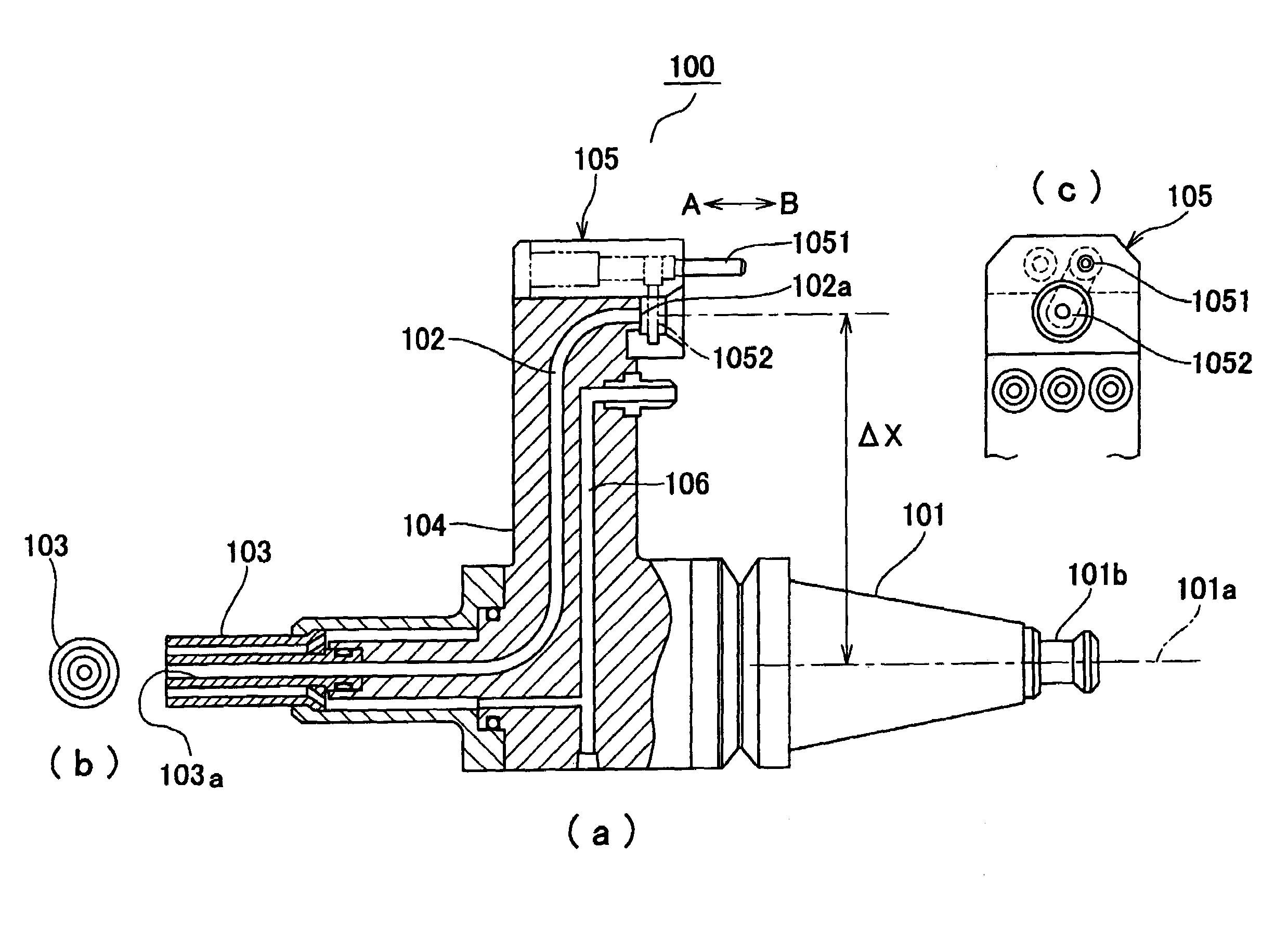
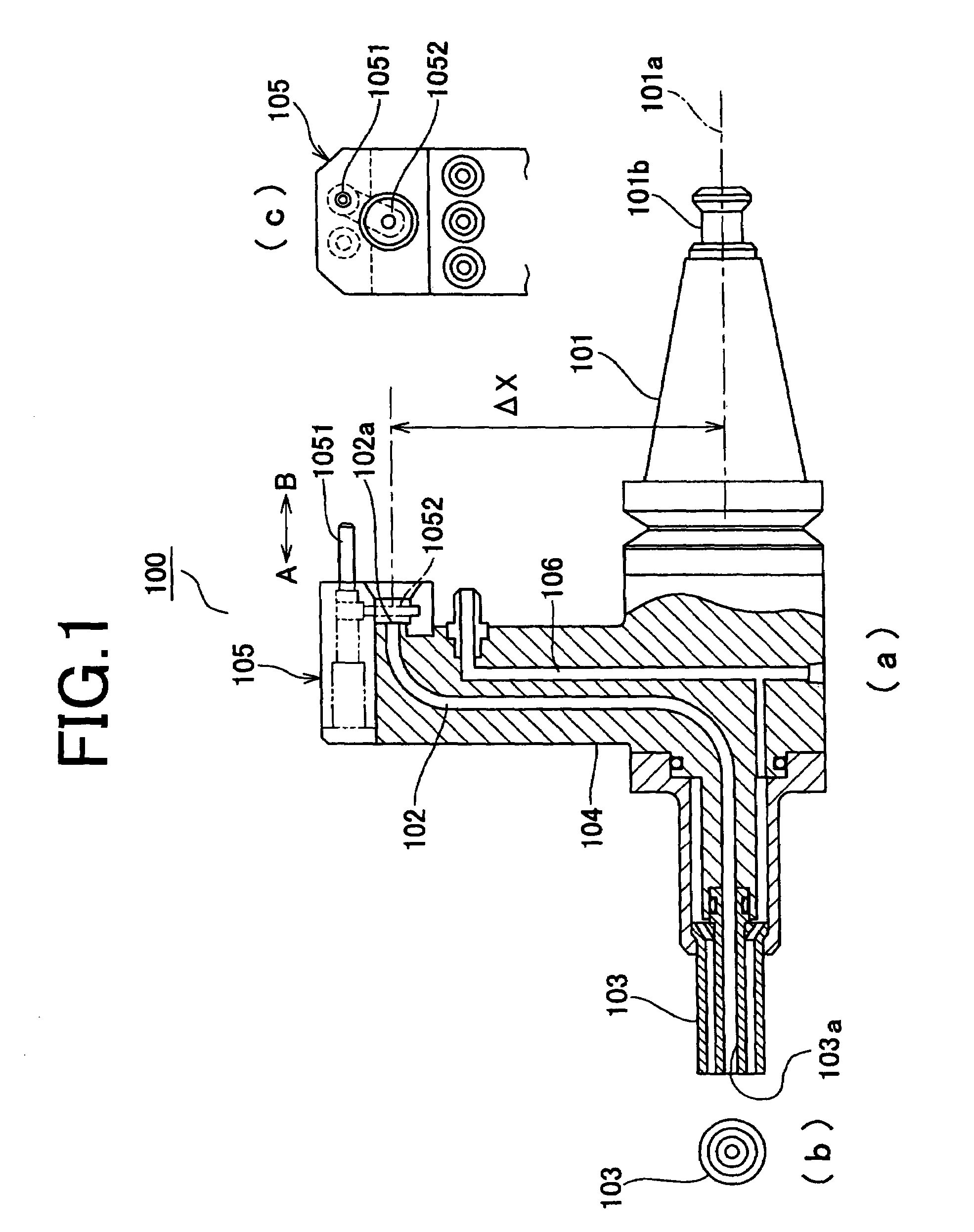
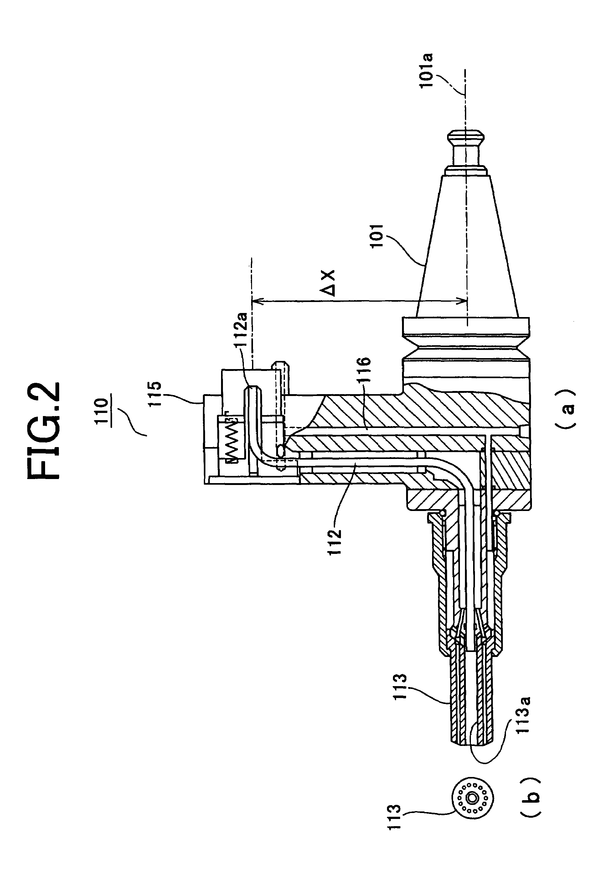
[0049]FIG. 1(a) is a partial sectional view showing a structure of a laser beam hardening tool according to the invention, FIG. 1(b) is a side view showing a structure of a torch portion 103, and FIG. 1(c) is a side view showing a structure of a shutter means 105, FIG. 2(a) is a partial sectional view showing a structure of another laser beam hardening tool according to the invention, FIG. 2(b) is a side view showing a structure of a torch portion 113, FIG. 3 is a sectional view showing a structure of a machine tool installing the laser beam hardening tool according to the invention therein, FIG. 4 is a view showing a structure of the shutter means for properly closing an end portion of a beam guide path (a path of laser beam) wherein (a) is a sectional view showing a state of a closed position, (b) is a sectional view showing a state of an opened position, and (c) is a side view showing a state of the closed position, and FIG. 5 is a sectional view showing a structure of the machin...


PUM

PropertyMeasurementUnit
diameteraaaaaaaaaa
diameteraaaaaaaaaa
diameteraaaaaaaaaa

Abstract

A laser beam hardening tool is comprised of an engagement portion for freely engaging with a tool holding portion of a machine tool, a beam guide path which is a passage of supplied laser beam, and a torch portion for radiating laser beam which passed through the beam guide path on a workpiece, thereby executing hardening with laser beam inside the machine tool by installing the laser beam hardening tool in the tool holding portion of the machine tool.

Description

BACKGROUND OF THE INVENTION[0001]The invention relates to a laser beam hardening tool formed so as to be freely attached to and detached from a tool holding portion of a machine tool.[0002]A machine tool capable of exchanging tools has been used, and various kinds of machining have been executed with such a machine tool (see Japanese patent application (Publication No. H11-77467).[0003]Both mechanical machining and hardening with laser beam on a surface of a workpiece are desired to be performed with such a machine tool, but a machine tool having a proper structure has not been proposed.[0004]An object of the invention is to provide a laser beam hardening tool formed so as to be freely attached to and freely detached from a tool holding portion of a machine tool.SUMMARY OF THE INVENTION[0005]One aspect of the invention is a laser beam hardening tool, comprising:[0006]an engagement portion capable of engaging with a tool holding portion of a machine tool;[0007]a beam guide path which...

Claims


Application Information

Patent Timeline
Patent Type & Authority Patents(United States)
IPC IPC(8): B23K26/00B23K26/064B23K26/60B23K26/352B23K26/70B23Q3/155B23Q11/08C21D1/09H01S3/00
CPCB23K26/0093B23K26/1482Y10T483/17
Inventor YAMAZAKI, TSUNEHIKOMIYAGAWA, NAOOMI
Owner YAMAZAKI MAZAK KK
Learn More