Disc indicator

a disc indicator and indicator technology, applied in the field of analog display instruments, can solve the problems of inability to make use of these instruments, less reliable operation of instruments such as these, and high manufacturing costs, and achieve the effects of reducing manufacturing costs, increasing sliding capability, and simplifying the bearing of the disc indicator

Inactive Publication Date: 2008-10-14
BORG INSTR +1
View PDF28 Cites 9 Cited by
  • Summary
  • Abstract
  • Description
  • Claims
  • Application Information

AI Technical Summary

Benefits of technology

[0008]The present instrument cluster provides an analog display instrument with a disc indicator, which has a simple and compact design and which offers high reliability with low-cost manufacture.
[0010]According to one exemplary embodiment, an analog display instrument is provided, in particular for use in dashboards in motor vehicles, having an indicator disc mounted such that a radial bearing allows the indicator disc to rotate. The indicator disc is fitted with a pointer which can be pivoted in front of a scale. The radial bearing comprises a sliding element and a guide element, with either of the slide element and the guide element having a ring structure and the other element having a holder which is suitable to hold the ring structure. The radial bearing is a journal bearing with the holder resting directly on a wall of the ring structure such that the ring structure may slide with respect to the holder.
[0013]The bearing for the disc indicator is greatly simplified. The simplification is achieved by mounting the indicator disc directly in a compact and robust holder. In this case, the disc indicator makes use of the discovery that the bearing for a pointer such as this is also subject to only relatively minor requirements, because of the relatively low rotation speeds and numbers of revolutions. Finally the instruments under discussion carry out only comparatively slow pivoting movements in the one direction and the other. These can be carried out even by “primitive” journal bearings, in which sliding elements and guide elements are manufactured from materials that are easy to machine, such as plastic. Furthermore, the production of disc indicators mounted in a simple manner such as these is not complex, and thus costs little, because the tolerances are relatively wide in comparison to heavily loaded journal bearings. Particularly in the case of minor loads such as these, there is no need for any increased sliding capability or for any cooling of the bearings in order to avoid wear. A further advantage is that a plurality of the disc indicators can be arranged one inside the other, and it is even possible for one indicator disc to form the bearing for the adjacent indicator disc.

Problems solved by technology

In consequence, the types of bearing specified for disc indicators are complex with a large number of components, resulting in correspondingly expensive manufacturing costs.
Furthermore, instruments such as these may be less reliable in operation.
Although disc indicators have a number of advantages over conventional instruments which have a pointer held at the end of a shaft, it has not until now been possible to make use of these instruments, particularly because of the high production costs.

Method used


Image

  • Disc indicator
  • Disc indicator
  • Disc indicator

Examples


Embodiment Construction

[0018]In the FIGURES, identical parts are provided with the same reference numbers and they are generally also only described once in each exemplary embodiment.

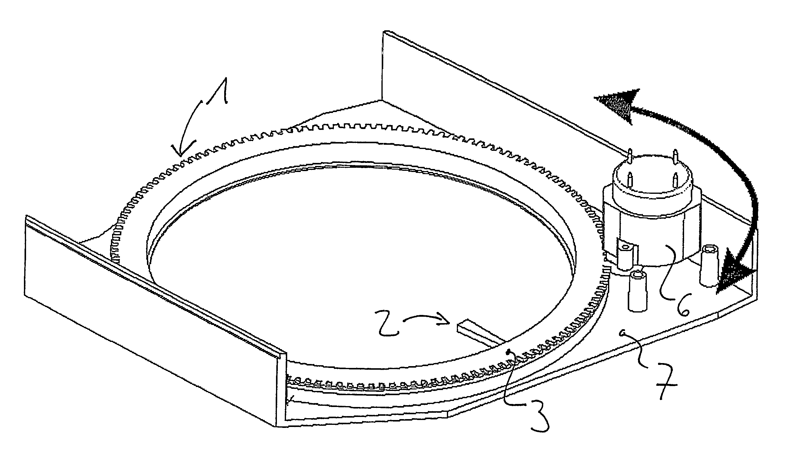
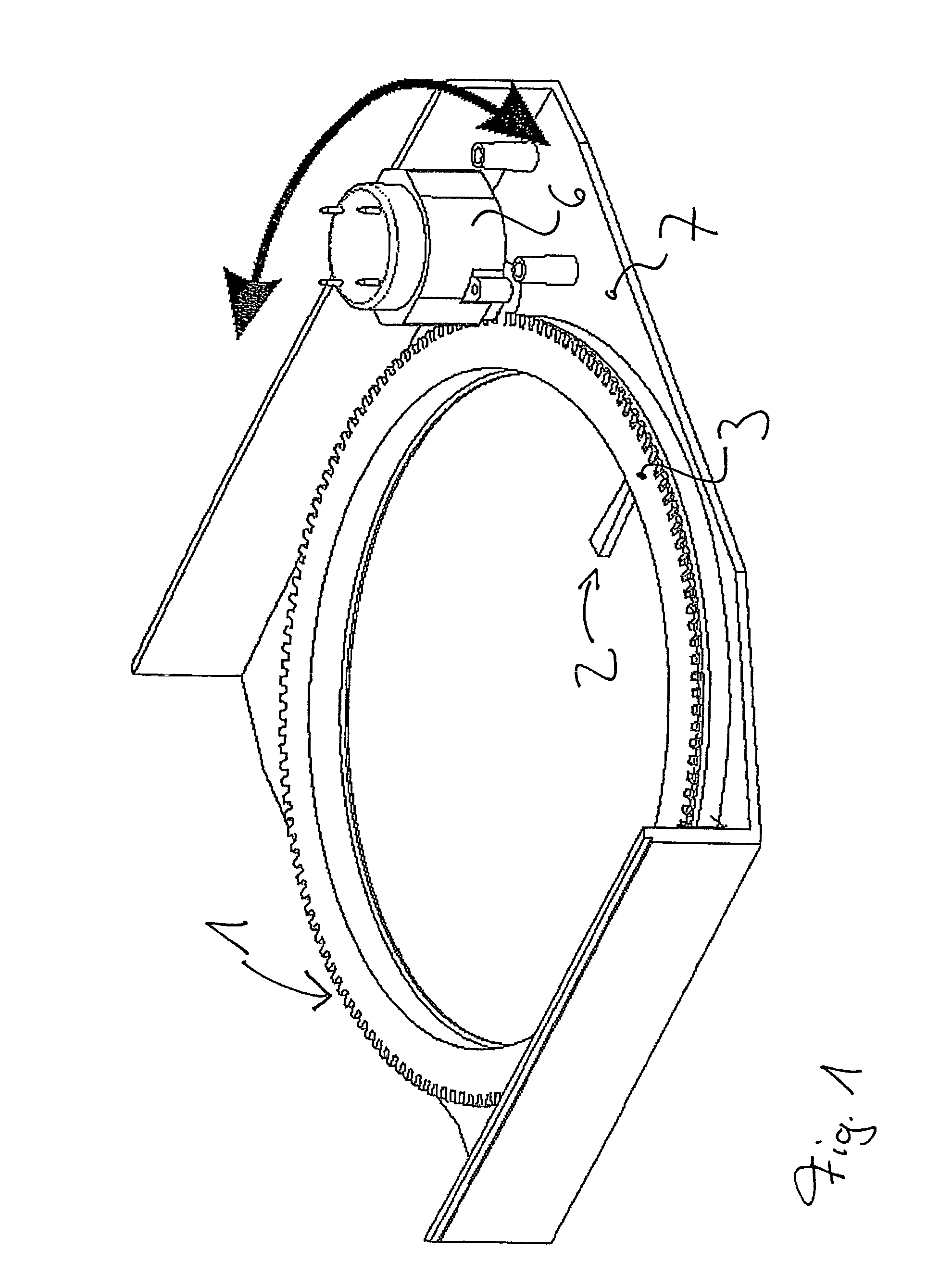
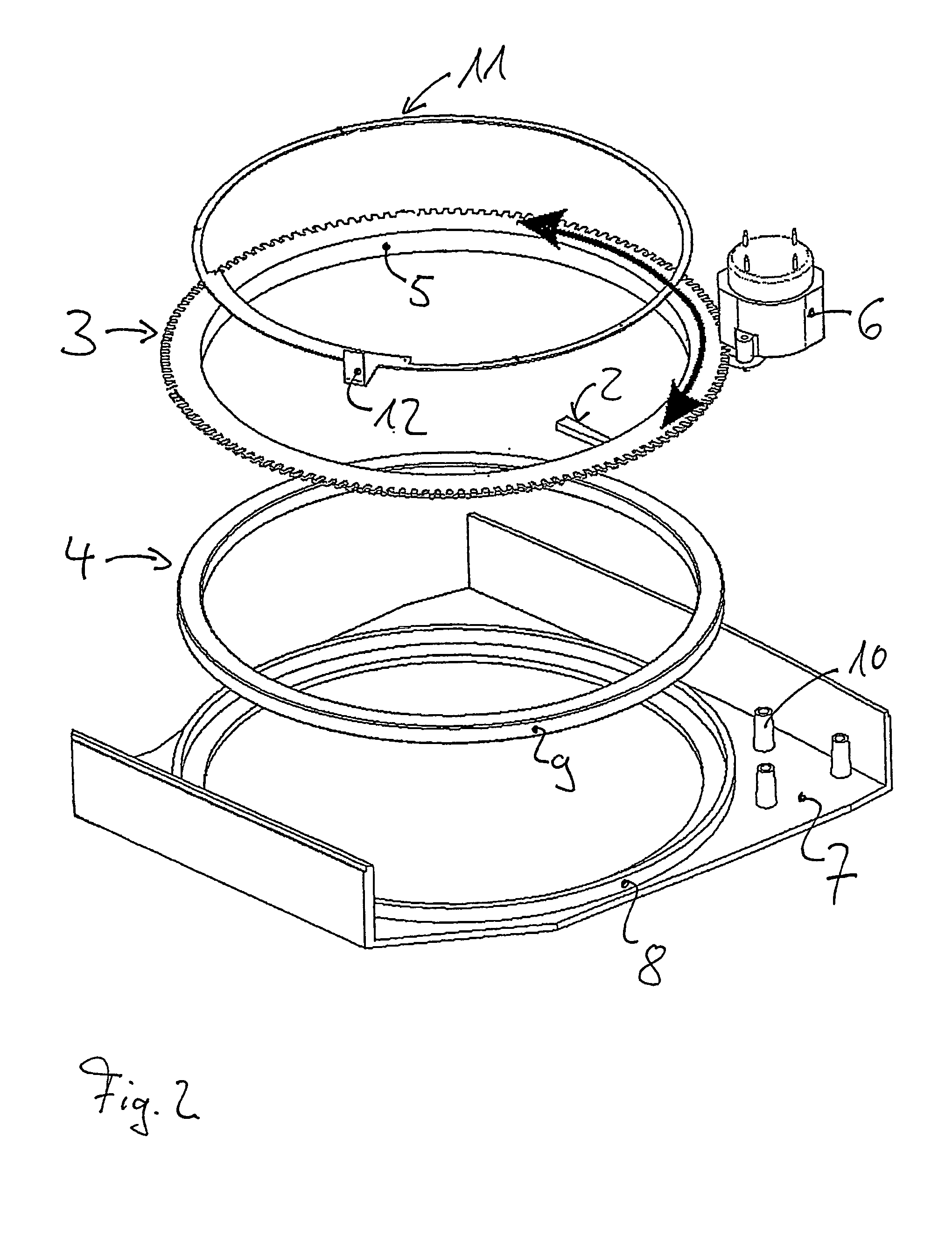
[0019]The indicator disc 1 is mounted by a radial bearing such that the radial bearing allows the indicator disc 1 to rotate. In this case, the radial bearing is a journal bearing of simple design, in which the indicator disc 1 forms the sliding element. The guide element is part of a front panel 7 of a combination instrument which, with a circular opening, forms a frame. A cylindrical holder 8 is integrally formed on the rear face of the front panel 7, as the bearing element. The holder 8 holds an appropriately cylindrically shaped ring structure of the indicator disc 1. In this case, the ring structure is a cylindrical attachment 9 which is integrally formed on the disc surface of the bearing ring 4. In the assembled state, the cylindrical attachment 9 engages in the cylindrical holder 8, with the walls of the two parts res...


PUM


Abstract

An analog display instrument is provided, in particular for use in dashboards in motor vehicles, having an indicator disc mounted by a radial bearing such that the radial bearing allows the indicator disc to rotate. The indicator disc is fitted with a pointer which can be pivoted in front of a scale. The radial bearing comprises a sliding element and a guide element, with either of the slide element and the guide element having a ring structure and the other element having a holder which is suitable to hold the ring structure. The radial bearing is a journal bearing with the holder resting directly on a wall of the ring structure such that the ring structure may slide with respect to the holder.

Description

CROSS-REFERENCE TO RELATED PATENT APPLICATIONS[0001]The present Application is a National Stage of Application PCT / EP2004 / 007502 entitled, “Disc Indicator” filed on Jul. 8, 2004 which published under PCT Article 21(2) on Jan. 20, 2005 as WO 2005 / 005931 A2 in the German language, which claims priority to German Patent Application No. DE 103 31 443 A1 filed on Jul. 10, 2003, the disclosures of which are incorporated herein by reference in their entirety.BACKGROUND[0002]The present invention relates to an analog display instrument, in particular for use in dashboards in motor vehicles.[0003]Disc indicators of this generic type have bearings for instruments on motor vehicles. In this case, the only instruments which are referred to as “disc indicators” in this context are those in which the indicator disc is not held on a shaft that is mounted such that it can rotate, but the indicator disc is mounted such that a guided ring structure allows the indicator disc to rotate. Finally, the sp...

Claims


Application Information

Patent Timeline
Patent Type & Authority Patents(United States)
IPC IPC(8): G01D13/04B60K35/00G01D13/22G12B11/04
CPCB60K37/02G01D13/04Y10S116/06B60K2370/6985
Inventor SUESS, MANFREDMAYER, MARTIN
Owner BORG INSTR
Why Eureka
Try Eureka