Pressurized actuator system for inflatable structures

a technology of pressure actuator and inflatable structure, which is applied in the direction of floats, pedestrian/occupant safety arrangements, packaging goods types, etc., can solve the problems of rotorcraft capsize, cable and pulley paint over, and not being properly tested and lubricated for movement,

Active Publication Date: 2008-10-14
AIR CRUISERS
View PDF28 Cites 26 Cited by
  • Summary
  • Abstract
  • Description
  • Claims
  • Application Information

AI Technical Summary

Problems solved by technology

When a pull handle or similar device associated with the system is activated, the valve is opened and the pressurized gas is discharged from the container and into the life raft causing its rapid inflation.
It should be noted however that such prior art deployment systems are typically adapted for deployment of a single inflatable structure and not necessarily concentrated simultaneous deployment of multiple inflatable structures.
Unbalanced deployment of the floatation devices could cause the rotorcraft to capsize and prevent the quick escape of passengers.
However, during aircraft maintenance procedures, the cables and pulle

Method used


Image

  • Pressurized actuator system for inflatable structures
  • Pressurized actuator system for inflatable structures
  • Pressurized actuator system for inflatable structures

Examples


Embodiment Construction

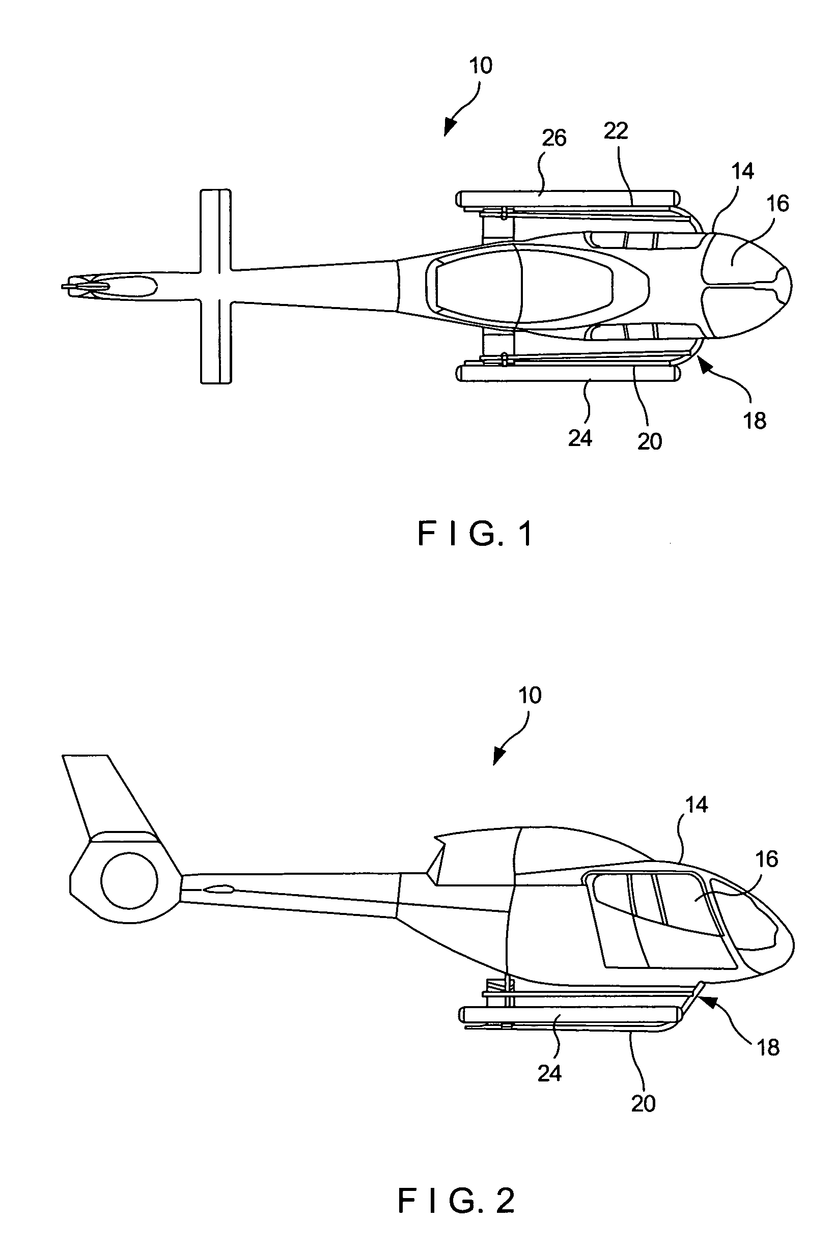
[0021]Referring now to the drawings in general, and to FIGS. 1 and 2 in particular, a rotorcraft or helicopter 10 employing a pressurized actuator system 12 (FIG. 3) in accordance with an exemplary embodiment of the present invention is illustrated. The rotorcraft 10 includes a main body 14 with a cockpit 16, a landing structure 18 having a first landing skid 20 and a second landing skid 22 which extend along a longitudinal axis of the rotorcraft and are in contact with the ground when not in flight. A pair of inflatable floatation devices 24 and 26 are connected to the first and second landing skids 20 and 22, respectively. It will be understood that more or less floatation devices can be provided on each leg and / or other parts of the rotorcraft 10.

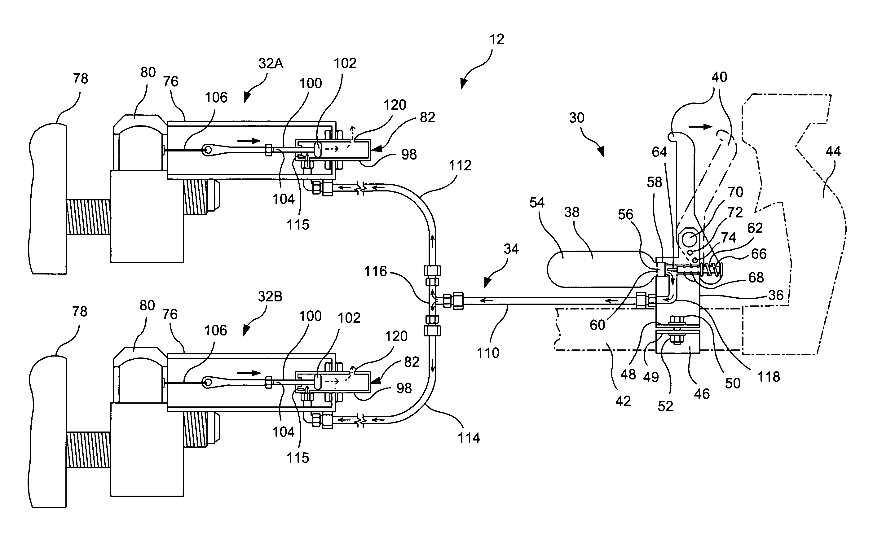
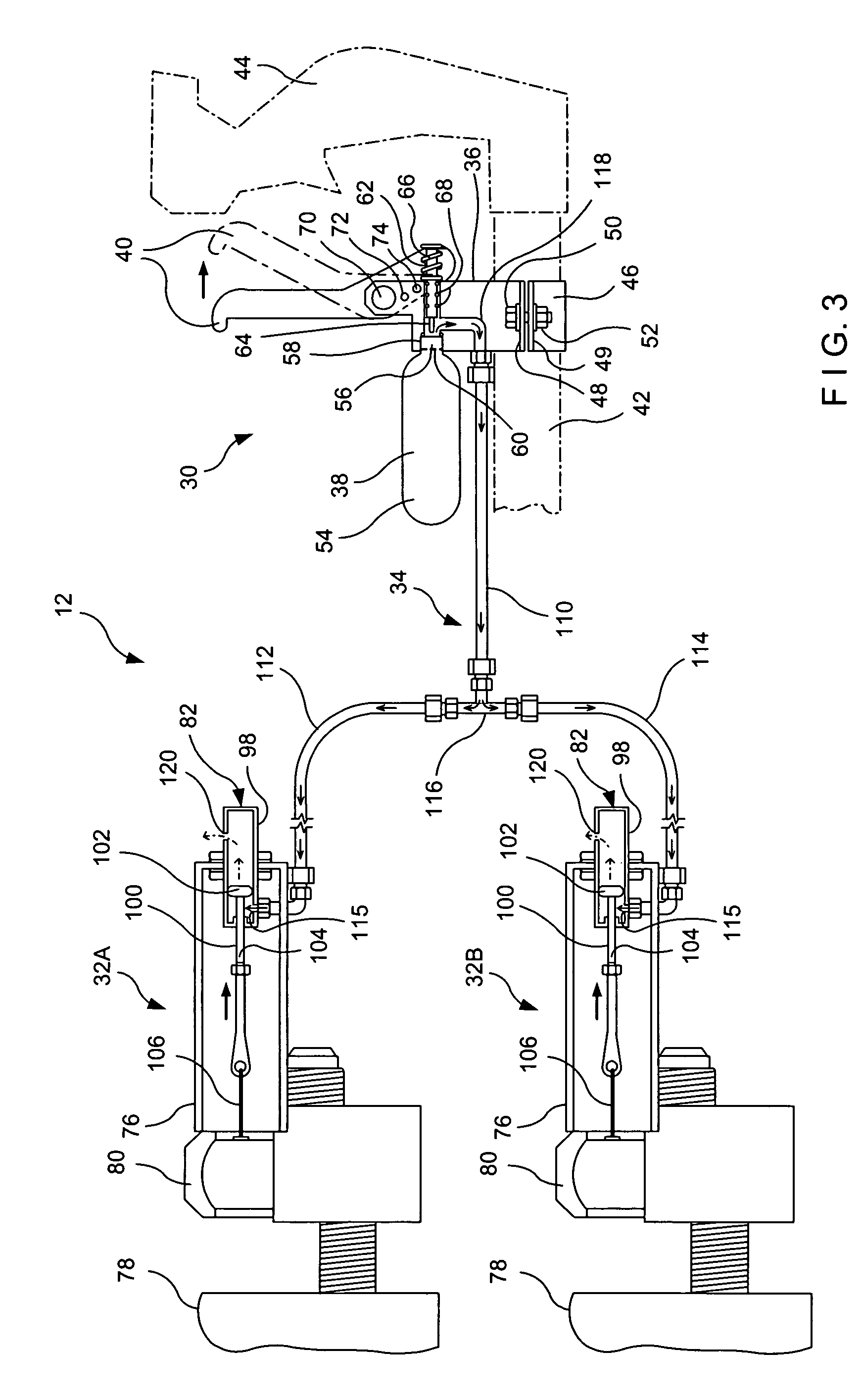
[0022]With additional reference to FIG. 3, the pressurized actuator system 12 includes an actuator portion 30 and a pair of deployment portions 32A, 32B that are fluidly connected to the actuator portion 30 through a pressure-resistant p...


PUM

PropertyMeasurementUnit
Pressureaaaaaaaaaa

Abstract

A pressurized actuator system for simultaneously deploying a plurality of inflatable floatation devices or other structures for a rotorcraft or other mobile or stationary devices includes a plurality of primary sources of pressurized fluid adapted for deploying a corresponding number of inflatable structures, a plurality of primary valves that are each operatively associated with one of the primary sources, a plurality of pressure-responsive primary transducers operative to open a different one of the primary valves, and a secondary source of pressurized fluid adapted for simultaneously operating the primary transducers to thereby open the primary valves and simultaneously deploy the plurality of inflatable structures.

Description

BACKGROUND OF THE INVENTION[0001]This invention relates to the deployment of inflatable structures, and more particularly to a pressurized actuator system that utilizes pneumatic or hydraulic force for initiating the reliable rapid deployment of inflatable structures and / or the simultaneous deployment of multiple inflatable structures.[0002]Certain types of aircraft, such as commercial fixed wing aircraft and rotorcraft such as for example, helicopters, are required by the regulatory agencies to carry inflatable floatation devices for passenger safety in the event of an emergency situation over water. Fixed wing commercial aircraft, for example, typically include one or more inflatable slides that are normally stored uninflated in a container mounted on the interior of the aircraft door or immediately adjacent thereto. With the door closed, a girt bar is connected to brackets on the floor inside the doorway such that it is only necessary to open the door to automatically deploy the ...

Claims


Application Information

Patent Timeline
IPC IPC(8): B65B1/08B60R21/26
CPCB64C25/56B64C25/52B64C2025/325
Inventor SWIERKOCKI, THOMAS W.HENRY, BRIAN
Owner AIR CRUISERS
Why Eureka
Try Eureka