Pilot-type two-port valve

a two-port valve, pilot-type technology, applied in the direction of valve details, valve arrangements, valve members for absorbing fluid energy, etc., can solve the problem of water hammer phenomenon during the closing of the valve, and achieve the effect of preventing water hammer

Inactive Publication Date: 2008-10-14
SMC CORP
View PDF5 Cites 21 Cited by
  • Summary
  • Abstract
  • Description
  • Claims
  • Application Information

AI Technical Summary

Benefits of technology

[0005]It is another object of the present invention to provide a pilot-type two-port valve arranged to restrict a discharge speed of pilot fluid for closing a valve to a lower value less than a supply speed of pilot fluid for opening valve for thereby effectively preventing a water hammer.
[0006]It is another object of the present invention to provide a pilot-type two-port valve arranged to enable the flow rate of discharging pilot fluid to be adjusted for thereby making it possible to adjust a speed of a valve member to close a liquid flow passage.
[0007]To address the above issues, the present invention provides a pilot-type two-port valve having a main valve mechanism including a first port and a second port serving as an inlet and an outlet for liquid, respectively, a valve seat formed in midstream of a main flow passage connected between both the ports, and a valve member operative to open or close the valve seat; and a valve drive mechanism including a piston, connected to the valve member via a rod, and first and second piston drive chambers formed on both sides of the pistons and operative such that supplying pilot fluid to or discharging the same from at least one of the first and second piston drive chambers allows the piston to operate for thereby opening or closing the valve member, wherein the two-port valve comprises a water hammer preventing mechanism operative to prevent the occurrence of water hammer resulting from the valve member closing the valve seat. The water hammer preventing mechanism has an orifice formed in the first piston drive chamber, from which fluid is discharged when the piston drives the valve member in a direction to close a valve, for limiting the flow rate of discharge fluid whereby when the valve member comes close to the valve set, the flow rate of the discharge fluid is restricted to the flow rate of fluid admitted through the orifice.
[0014]Thus, according to the present invention, a simplified mechanism can stably prevent water hammer from occurring during valve-closing operation. More particularly, the pilot-type two-port valve is arranged to limit a discharge speed of pilot fluid for the closing of a valve to a lower value less than a supply speed of pilot fluid for the opening of the valve whereby water hammer can be effectively prevented while making it possible to adjust the flow rate of pilot fluid being discharged to enable the adjustment of a speed of the valve member to close the liquid flow passage.

Problems solved by technology

With the pilot-type two-port valve of such a kind, the valve is closed at a relatively high speed and using such a two-port valve in a liquid flow passage remaining at a relatively high pressure results in the occurrence of a water hammer phenomenon during the closing of the valve.

Method used


Image

  • Pilot-type two-port valve
  • Pilot-type two-port valve
  • Pilot-type two-port valve

Examples


first embodiment

[0043]Now, the operation of the first embodiment mentioned above is described below.

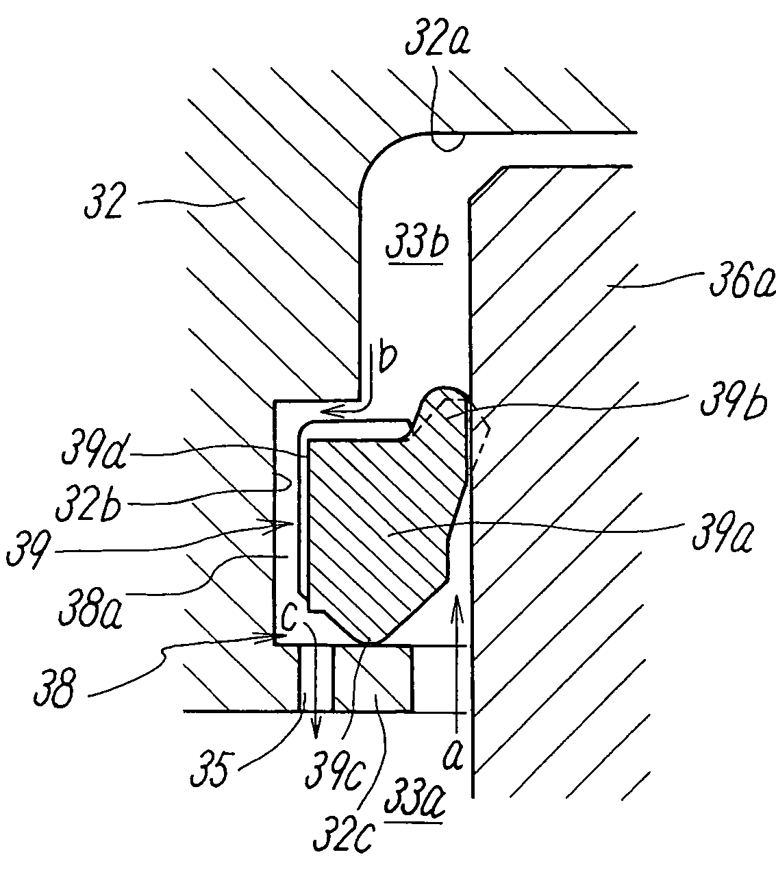
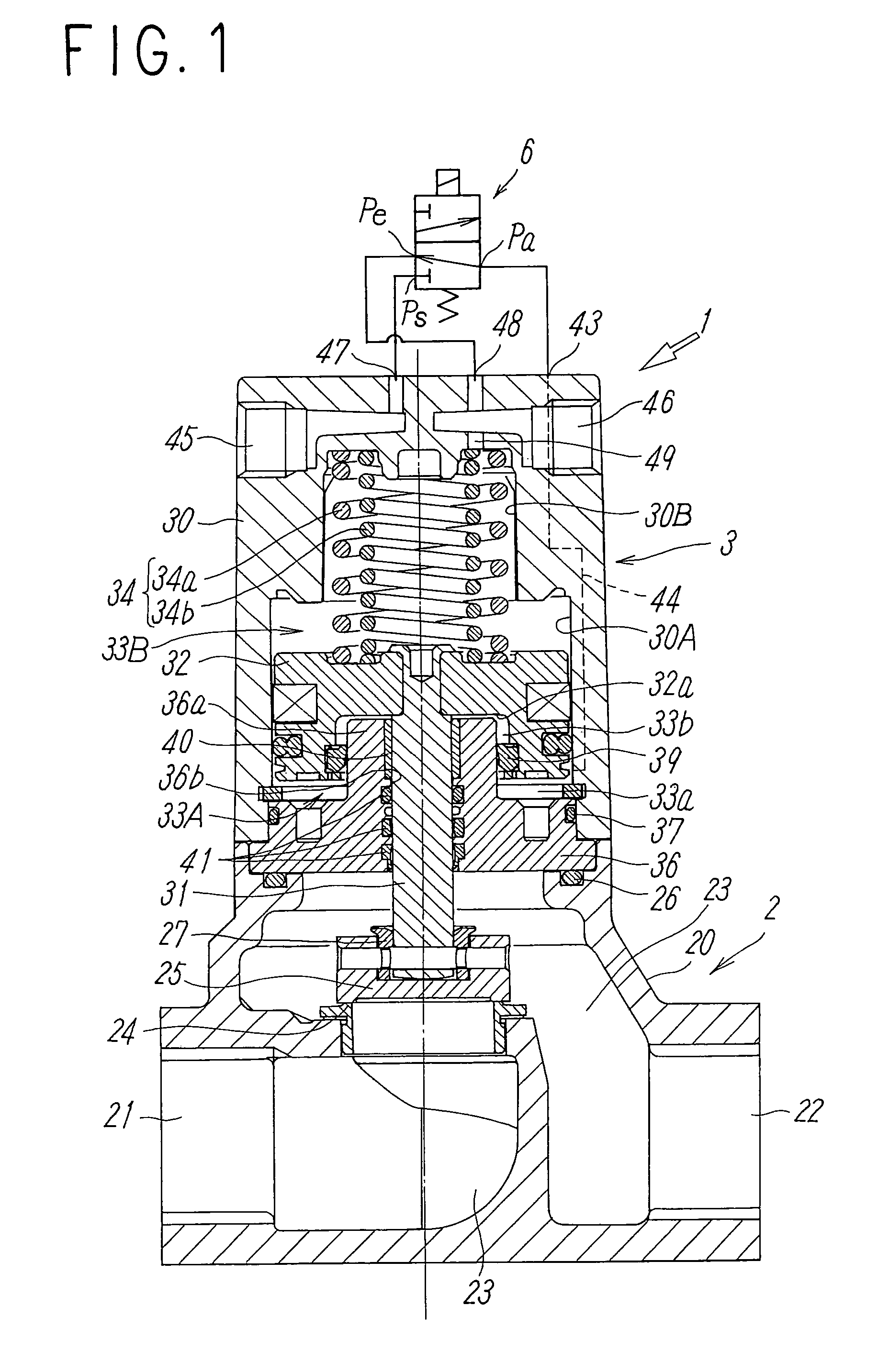
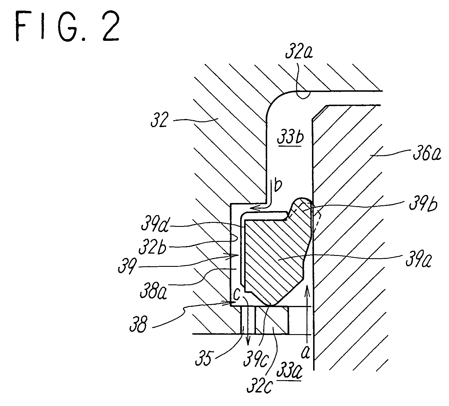
[0044]As shown in FIG. 1, when opening the main flow passage 23 with the valve in closed state wherein the valve member 25 is held in abutting contact with the valve seat 24, the pilot valve 6 is energized to cause the inlet port Ps to communicate with the outlet port Pa. This allows pilot fluid to flow into the piston pressure chamber 33a of the first piston drive chamber 33A via the pilot flow passage 44, after which pilot fluid acts on the lip portion 39b of the seal member 39 to push open the same and flows into the damper chamber 33b. Simultaneously, pilot fluid passes through the orifice 35 into the damper chamber 33b through the devious flow passage 38a. Then, pilot fluid under pressure reached the piston pressure chamber 33a and the damper chamber 33b drives the piston 32 against a spring force of the resilient member 34. This allows the rod 31 to move the valve member 25 away from the valve ...

second embodiment

[0053]With the second embodiment, a guide flow passage 58 is comprised of an opening and closing flow passage 58a, in which a one-way seal member 59 is disposed, and a devious flow passage 58b formed in the columnar section 36a of the plate 36 so as to bypass the flow passage 58a. The devious flow passage 58b has an outlet provided with an orifice 55 for limiting the flow rate of fluid. The seal member 59, made of resilient rubber material and formed in a ring shape with a V-shape configuration in cross section, includes an outer wall 59a held in tight contact with the inner peripheral wall of the recessed portion 32b of the piston 32, a base portion 59b held in tight contact with the annular flange portion 32c of the piston 32, and a lip portion 59c obliquely extending from the base portion 59b toward a circumferential periphery of the columnar section 36a of the plate 36.

[0054]The devious flow channel 58b, provided with the orifice 55, is formed in the columnar section 36a at an a...

third embodiment

[0057]Next, description is made of a pilot-type two-port valve according to the present invention with reference to FIGS. 7 to 10.

[0058]The two-port valve of the third embodiment differs from the second and third embodiments in the valve drive mechanism 3 in respect of the means for limiting a discharge speed of pilot fluid for the closing of a valve in proportion to a supply speed of pilot fluid for the opening of the valve and no difference exists in other structures. Therefore, description is made with a focus on the above different points while the same component parts bear the same reference numerals as those of the first embodiment and description of the same is herein omitted.

[0059]Further, although the pilot valve 6 and the flow channel plate 7 can be selectively utilized, description and illustration of these component parts are herein omitted.

[0060]A two-port valve 11 of the third embodiment, shown in FIG. 7, has the main valve mechanism 2 that is not substantially differe...


PUM


Abstract

A pilot-type two-port valve is disclosed having a water hammer preventing mechanism, operative to prevent a water hammer during valve-closing operation, which includes a valve member operative to open or close a valve and a piston driven by pilot fluid for operating the valve member for opening and closing movements. The water hammer preventing mechanism comprises a piston drive chamber, from which fluid is discharged during valve-closing operation, which has an orifice for restricting the flow rate of discharge fluid whereby when the piston moves to a position to allow the valve member to be close to a valve seat, a portion of an discharge flow passage of the piston drive chamber is blocked to restrict the flow rate of the discharge fluid to the flow rate of fluid flowing through the orifice.

Description

TECHNICAL FIELD[0001]The present invention relates to pilot-type two-port valves mounted in liquid flow passages for opening or closing the same and, more particularly, to a pilot-type two-port valve used in a liquid flow passage for coolant or the like for preventing water hammer resulting from the closing of a valve.[0002]In the related art, a pilot-type two-port valve has been known, as disclosed in Japanese Unexamined Patent Application Publication No. 2001-193846, wherein a valve member, operative to be seated on or unseated from a valve seat disposed in a liquid flow passage, is moved in a valve-opening direction upon supply of pilot fluid to a pressure-acting chamber formed on one side of a piston to discharge pilot fluid for enabling the piston to move in a valve-closing direction due to an urging force of a coil spring.[0003]With the pilot-type two-port valve of such a kind, the valve is closed at a relatively high speed and using such a two-port valve in a liquid flow pass...

Claims


Application Information

Patent Timeline
Patent Type & Authority Patents(United States)
IPC IPC(8): F16K31/12
CPCF16K31/1221F16K31/124F16K47/023F16K31/1225
Inventor HAYASHI, BUNYAMIYAZOE, SHINJIYOSHIMURA, SHINICHI
Owner SMC CORP
Why Eureka
Try Eureka