Pest deterrent fence

a technology of deterrent fences and pests, applied in the field of pest deterrent fences, can solve the problems of ineffective barrier, rapid depletion of battery power sources, and deterring the animal from further progress, and achieve the effect of promoting moisture beading and falling

Inactive Publication Date: 2008-10-14
CONTECH ELECTRONICS
View PDF10 Cites 27 Cited by
  • Summary
  • Abstract
  • Description
  • Claims
  • Application Information

AI Technical Summary

Problems solved by technology

This deters the animal from further progress.
A common problem associated with this type of fencing apparatus is that moisture in the form of rain or dew is able to create a current pathway across the non-conducting surface by wetting the entire non-conducting surface.
This renders the barrier ineffective at a time when these animals are most active, that is, in moist conditions.
As well, since the fence is effectively shorted, a battery power source will become quickly depleted.

Method used


Image

  • Pest deterrent fence
  • Pest deterrent fence
  • Pest deterrent fence

Examples


Embodiment Construction

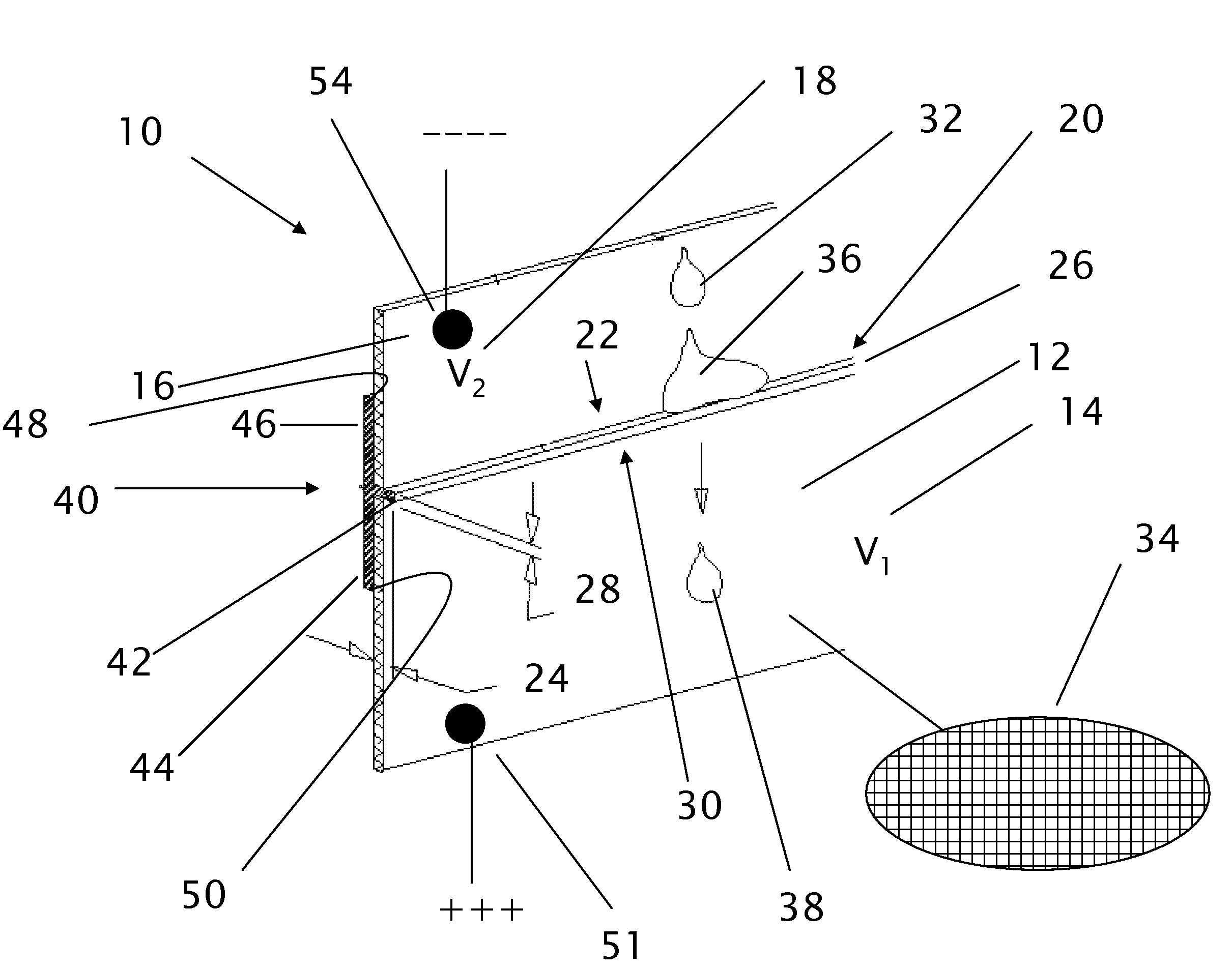
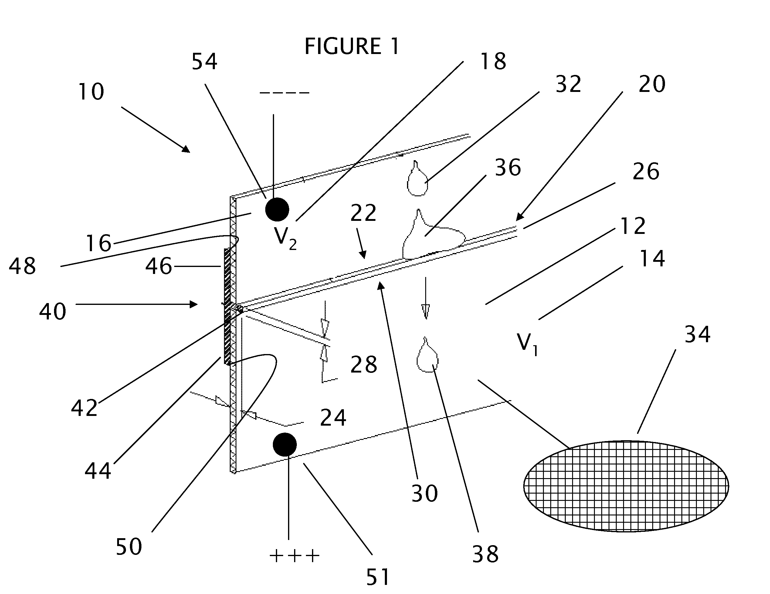
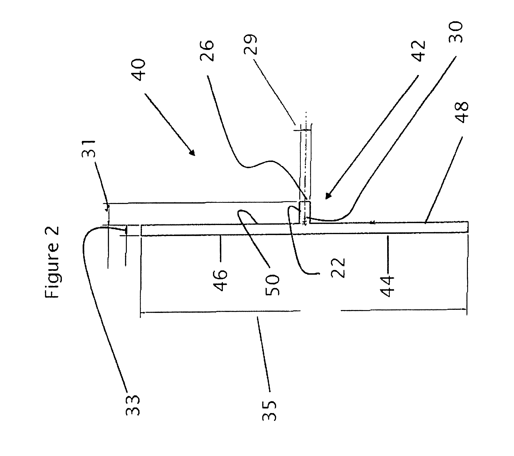
[0019]Referring to FIG. 1, my invention (10) is a pest deterrent fence to keep snails, slugs, worms and similar garden pests away from plants. Problems associated with previous known deterrent fences of this type include the wetting of the dielectric between conducting surfaces to such an extend that there is a current rack between them. This results in the same voltage on both sides of the dielectric and renders the fence ineffective in wet climates or other areas with heavy humidity and dew. It also results in excessive power use and battery depletion. Through much experimentation in the wet climates of Vancouver Island, I have discovered that a certain type and configuration of dielectric resists wetting and causes excessive moisture to bead and drop from the dielectric of my invention without contacting both sides of the dielectric.

[0020]My invention comprises a first conductive surface (12) having a first voltage potential V1 (14) and a second conductive surface (16) having a s...


PUM


Abstract

A pest deterrent fence is used to deter slugs and snails and similar animals from gaining access to gardens. The fence comprises vertically oriented first and second conductive surfaces that are generally metallic mesh. The conductive surfaces separated by a polyvinylchloride non-polar dielectric. The dielectric is “T” shaped and is dimensioned such that it prevents moisture from connecting the first and second conductive surfaces by promoting beading and dripping.

Description

FIELD OF THE INVENTION[0001]This invention generally relates to fences carrying an electrical current to deter or repel the movement of animals; and, vermin destroying apparatus such as a structure which repels or deters the movement of animal life. Specifically, this invention relates to a pest deterrent fence.BACKGROUND OF THE INVENTION[0002]Snails and slugs are well known garden pests. One way of dissuading their encroachment into gardens is to set an electrified fence in their path. There are many such devices in the known art such as that disclosed in U.S. Pat. No. 4,756,116 “Snail Barrier” issued to Cutter on Jun. 12, 1998. This type of fence generally comprises a first and second conducting surfaces separated by a non-conducting surface having a width less than the length of the animal. The animal attempts to cross the non-conducting surface and contacts both conducting surfaces causing an electrical current to flow through the animal. This deters the animal from further prog...

Claims


Application Information

Patent Timeline
Patent Type & Authority Patents(United States)
IPC IPC(8): A01M1/24
CPCA01K3/00A01K67/0331A01M29/28
Inventor FOSTER, MARK
Owner CONTECH ELECTRONICS
Why Eureka
Try Eureka