Automatic wheelchair brake system and wheelchair including same

a brake system and automatic technology, applied in the direction of brake systems, wheelchairs/patient conveyance, transportation and packaging, etc., can solve the problems of insufficient manual brakes, patient is extremely vulnerable to falling injuries, and cannot be easily installed and operated, so as to facilitate easy folding and storage, facilitate easy installation, and facilitate the effect of convenient folding

Inactive Publication Date: 2008-10-14
AIR MOVEMENT TECH
View PDF34 Cites 13 Cited by
  • Summary
  • Abstract
  • Description
  • Claims
  • Application Information

AI Technical Summary

Benefits of technology

[0017]It is an object of the present invention to overcome the drawbacks in the prior art, particularly to provide an automatically engageable and releasable wheelchair brake having few components to facilitate easy installation, having a nonrestrictive installed structure to facilitate easy folding and storage, and having a comfortable and effective means of preventing unwanted motion, such as rollback, of the wheelchair especially while users transition from a sitting position to a standing position, or vice versa.
[0018]According to one embodiment of the present invention, an automatically engageable and releasable brake apparatus adaptable to be attached to a wheelchair is provided. The brake apparatus includes a connection mechanism adapted to be positioned directly on a portion of the wheelchair frame proximate a rear wheel of the wheelchair, a seat actuation member adapted to be positioned on a surface of the wheelchair seat, and a brake actuating member in fluid communication with the seat actuation member defining a closed fluid system therewith. The brake actuating member is coupled to the connection mechanism and further includes a brake member adapted to contact the ground surface on which the wheelchair is located. The brake member is coupled to the brake actuating member such that occupational ingress into the wheelchair i.e., when a person assumes a seated position in the wheelchair seat or an object is placed thereon, actuates the seat actuation member. Fluid is transferred from the seat actuation member to the brake actuating member to thus actuate the brake actuating member. This, in turn, causes the brake member to move from a first position in substantial contact with the ground surface on which the wheelchair is located to a second position spaced a distance above the ground surface.
[0019]Furthermore, occupational egress, i.e., when a user or an object vacates the wheelchair seat, essentially deactivates the seat actuation member, which in turn deactivates the brake actuating member and causes the brake member to move from the second position spaced a distance above the ground surface to the first position in substantial contact with the ground surface. Thus, when the wheelchair seat is occupied upon ingress, the brake member is in the second position, which permits uninhibited rearward motion of the wheelchair and allows the wheelchair to move both forward and backward at the user's discretion. When the wheelchair seat is vacated upon egress, the brake member assumes the first position in contact with the ground surface, which stabilizes the wheelchair and prevents rearward motion.

Problems solved by technology

But often, getting in and out of the wheelchair can pose a problem for such users, in that the chair may roll backward unexpectedly as the patient transitions from standing to sitting, and vice versa.
Further, because only a minimal force is required to move the wheelchair backwards rather rapidly, the patient is extremely vulnerable to falling injuries during this transition period.
However, when the user is severely handicapped or otherwise unable to operate the hand brake, manual brakes are quite inadequate.
An unaided user who attempts to enter or exit a wheelchair that is not locked in a stationary position is faced with a difficult and dangerous task.
However, despite its popularity, this brake causes unnecessary tire tread wear, lacks substantial holding efficiency on sloped surfaces, and becomes almost unusable when the tire is wet.
Since the device is only applied to one wheel, applying stopping action on both wheels of the wheelchair requires installation of two devices that must be engaged using two hands, which may not be an available option for a particular patient.
However, the threat of rollback remains after the wheelchair is freely repositioned, especially if an unaided patient forgets to re-engage the manual-lock before sitting, or another unaware patient attempts to sit in the unbraked wheelchair.
Thus, despite the automatic engagement feature, the manual nature of this brake is not generally desirable for seriously impaired patients.
In most cases, when the wheel axle bolt is removed from the wheelchair, the wheel requires substantial bracing to avoid complete removal, due to the fact that the removed axle bolt can no longer secure the wheel to the wheelchair.
Ultimately, installation is time consuming and complex.
Particularly, one problem is that the above mentioned automatic wheelchair brakes include a multitude of small parts which must be precisely adjusted to work in concert to accomplish the desired effect.
Many people who are responsible for wheelchair operation and maintenance are thus hesitant to tackle such complex installation of multi-component brakes.
Portability and storage of unoccupied wheelchairs are also hindered by complex automatic brake assemblies that usually brace the frame of the wheelchair in a transverse manner.
Given the complex nature of the multiple-component assemblies, foldable storage and transport is not easily facilitated.
Another common problem among automatic wheelchair brake mechanisms is that the safety feature itself compromises the comfort of the user.
Thus, patients seated in thusly equipped flexible wheelchair seats often experience discomfort or pain due to the presence of the brake activation member pushing up on the seat.
This can be annoying for any patient, but can pose particularly serious problems, such as skin deterioration, for those who spend a considerable amount of time in the wheelchair.

Method used


Image

  • Automatic wheelchair brake system and wheelchair including same
  • Automatic wheelchair brake system and wheelchair including same
  • Automatic wheelchair brake system and wheelchair including same

Examples


Embodiment Construction

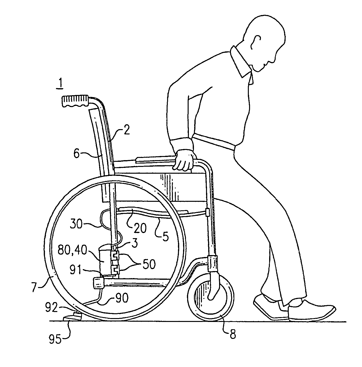
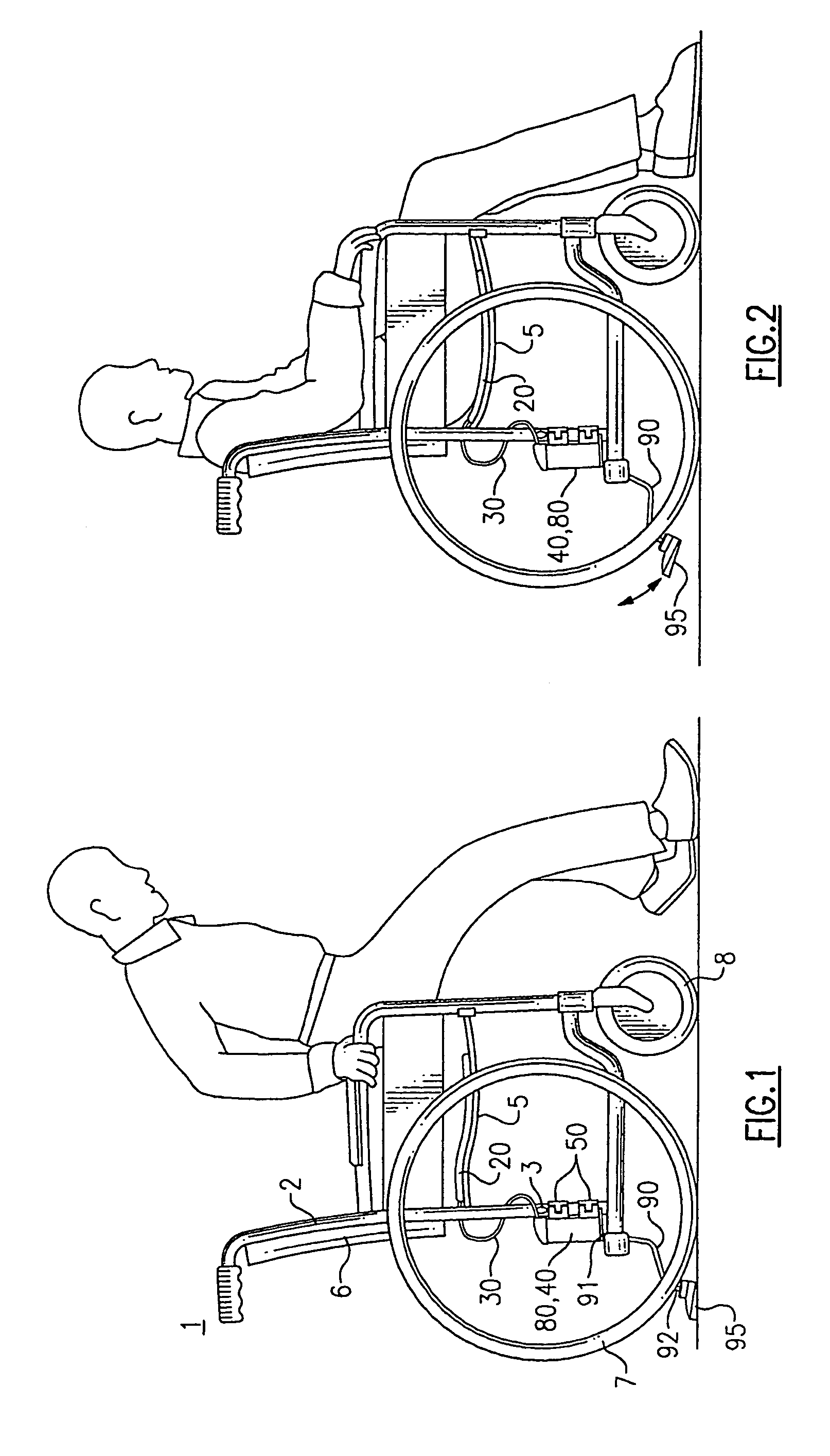
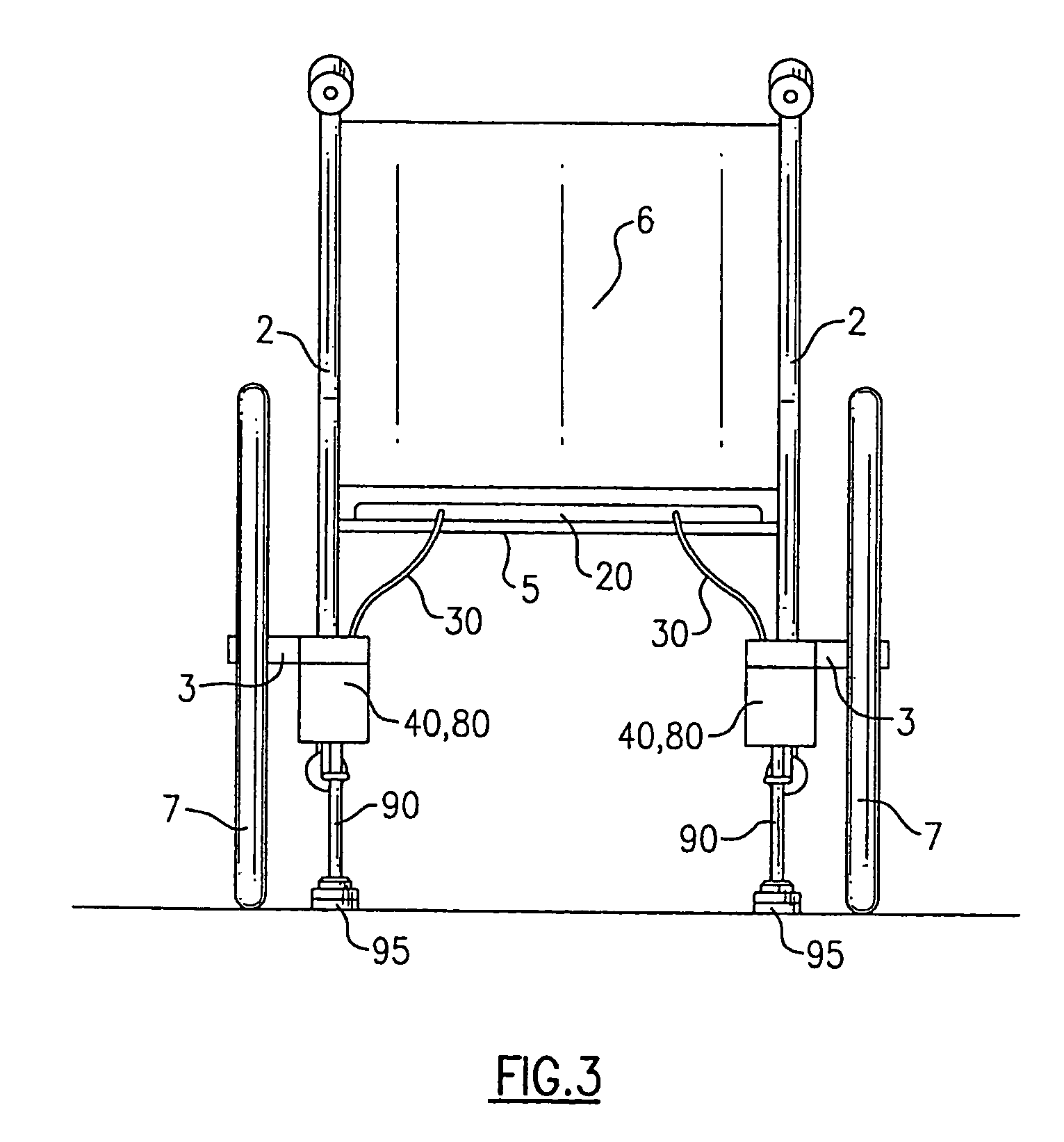
[0055]FIG. 1 is a side view of a wheelchair and an engaged mode of a brake apparatus according to one embodiment of the present invention, specifically shown as an occupant attempts to sit on the seat member 5 of the wheelchair 1. The brake apparatus of this embodiment includes a compressible seat actuation member 20 positioned on the seat member 5, which is coupled with a brake actuating member 80 via a conduit 30 to comprise a closed fluid system. The brake actuating member 80 is housed within a connection mechanism 40, which is affixed to the wheelchair 1 at a rear portion of the frame 2 via integrated attachment members 50, 50 and vertically spaced a distance below the axle 3 of rear wheel 7.

[0056]The brake apparatus further includes a brake shaft member 90 extending downwardly from a first end 91 proximate the connection mechanism 40 toward an opposed second end 92. A friction member 95 is also included proximate the second end 92 of the brake shaft member 90, and positioned to...


PUM


Abstract

An automatically engageable and releasable brake apparatus adaptable to be attached to a wheelchair is provided, including a connection mechanism adapted to be positioned on a rear frame portion of the wheelchair frame, a seat actuation member adapted to be positioned on the wheelchair seat, a brake actuating member coupled to the connection mechanism and in fluid communication with the seat actuation member defining a closed fluid system therewith, and a brake member coupled to the brake actuating member and adapted to contact a ground surface on which the wheelchair is located. Occupational ingress into the wheelchair causes fluid to flow from the seat actuation member to the brake actuating member, which causes the brake member to move from a first position in substantial contact with the ground surface on which the wheelchair is located to a second position spaced a distance above the ground surface.

Description

BACKGROUND OF THE INVENTION[0001]The present invention relates to an automatic wheelchair brake system for preventing unwanted rearward movement of a wheelchair during an occupant's transitional ingress and egress, and more particularly to a wheelchair having a brake apparatus that automatically releases when a patient is properly seated.[0002]Using a wheelchair enables patients suffering from various physical and mental disabilities to engage in some level of activity without experiencing the pain or limitations ordinarily placed upon them, and many patients who use wheelchairs are not permanently confined thereto. For these patients, the wheelchair is a convenient tool to facilitate mobility that is not possible otherwise. But often, getting in and out of the wheelchair can pose a problem for such users, in that the chair may roll backward unexpectedly as the patient transitions from standing to sitting, and vice versa. It is especially important that the wheelchair remains statio...

Claims


Application Information

Patent Timeline
Patent Type & Authority Patents(United States)
IPC IPC(8): A61G5/10B60T7/14B62B5/04F16D65/14B60T1/14
CPCA61G5/1029B60T1/14A61G5/101A61G5/1035B62B5/049
Inventor CONNORS, JAMES B.ILES, EDWARDFAMULARE, FRANKLI, YUAN JIANZHANG, MORGAN
Owner AIR MOVEMENT TECH
Why Eureka
Try Eureka