Liquid transporting apparatus and method for producing liquid transporting apparatus

a technology of liquid transporting apparatus and liquid transporting head, which is applied in the field of liquid transporting head, can solve the problems of lowering the printing quality of ink-jet head, reducing the energy efficiency of piezoelectric actuator, etc., and achieves excellent durability, enhanced printing quality, and satisfactory energy efficiency

Active Publication Date: 2008-10-14
BROTHER KOGYO KK
View PDF13 Cites 2 Cited by
  • Summary
  • Abstract
  • Description
  • Claims
  • Application Information

AI Technical Summary

Benefits of technology

[0011]The present invention is made to solve the abovementioned problems, an object of which is to provide a piezoelectric actuator, a fluid transporting apparatus and an ink-jet head which are capable of applying a sufficient amount of deformation to the piezoelectric material plate even when the surface area of piezoelectric material arranged between the electrodes is decreased; in which the deformation of the portion of the actuator, corresponding to one of the pressure chambers, is prevented from affecting other portion of the actuator corresponding to another pressure chamber; in which the printing quality can be enhanced and a satisfactory energy efficiency can be realized. Another object of the present invention is to provide a liquid transporting apparatus provided with a piezoelectric actuator which has excellent durability and in which the driving efficiency is further enhanced, and a method for producing such a liquid transporting apparatus.
[0014]In the liquid transporting apparatus of the present invention, each of the individual electrodes in the piezoelectric actuator is arranged at the area overlapping with the edge portion of one of the pressure chambers. Accordingly, when a drive voltage is applied to one of the individual electrodes, a portion of the piezoelectric layer, which is sandwiched between the individual electrode and the common electrode and is along the edge portion of one of the pressure chambers is contracted in a direction parallel to the plane of the piezoelectric layer. As a result, the vibration plate and the piezoelectric layer are archingly deformed to project toward a side opposite to one of the pressure chambers, with the portion of the piezoelectric layer overlapping with the central portion of one of the pressure chamber as apex of the archingly deformation, thereby increasing the volume of the pressure chamber and generating a pressure wave inside the pressure chamber. Further, when the application of drive voltage to the individual electrode is stopped at timing when the pressure wave in the pressure chamber changes to positive in the pressure chamber, the vibration plate is restored to the initial or original shape, thereby reducing the volume inside the pressure chamber. However, at this time, the pressure wave generated with the increase in the volume of the pressure chamber and the pressure wave generated with the restoration of the vibration plate are combined and a substantial pressure is applied to the liquid in the pressure chamber. Therefore, it is possible to apply a substantial pressure to the liquid with a comparatively low drive voltage, thereby improving a drive efficiency of the piezoelectric actuator. Moreover, since the electric field is made to act on the piezoelectric layer by applying the drive voltage to the individual electrodes only at a timing of ink transportation, polarization deterioration hardly occurs in the piezoelectric layer, and accordingly the durability of the actuator is improved.
[0015]Further, when the value of A / (W / 2) is within a range of not less than 0.33 to not more than 0.75 wherein W is the length in the radial direction of the pressure chambers (a length of the pressure chambers in a direction of a straight line passing through the center of surface area of the pressure chambers), and A is the length in the radial direction of portions of the individual electrodes, each of the portions overlapping with one side portion, in the radial direction, of the edge portion of one of the pressure chambers, then it is possible to deform the piezoelectric layer more greatly while suppressing the variation in the amount of deformation of the piezoelectric layer, thereby improving the driving efficiency of the piezoelectric actuator.
[0016]In the liquid transporting apparatus of the present invention, the value of A / (W / 2) may be not less than 0.41 and not more than 0.69, and the value of A / (W / 2) may be not less than 0.41 and not more than 0.55. In this manner, when the length A in the radial direction of the individual electrodes are small within the range of the value of A / (W / 2) in the liquid transporting apparatus of the present invention, it is possible to make capacitance generated in the piezoelectric layer between the individual electrodes and the common electrode to be small while increasing the amount of deformation of the piezoelectric layer, thereby making the power consumption of the piezoelectric actuator to be small.
[0017]In the liquid transporting apparatus of the present invention, each of the pressure chambers may have a shape long in a predetermined direction; and each of the individual electrodes may be formed at least at two areas which are included the area which overlaps with the edge portion of one of the pressure chambers and which extend substantially in parallel to the predetermined direction. When each of the pressure chambers has a shape which is long in a predetermined direction, a length of the individual electrodes in a direction, which intersects the longitudinal direction (the predetermined direction) of the pressure chamber, greatly affects the amount of deformation of the piezoelectric layer. For this reason, the length A of the individual electrodes, each of which is formed at least in two areas which are included in the area overlapping with the edge portion of one of the pressure chambers and which extend in the longitudinal direction of one of the pressure chambers, the length being in the direction intersecting the longitudinal direction (corresponding to the radial direction in the liquid transporting apparatus of the present invention) of the pressure chamber, is made to have an appropriate value such that the amount of deformation of the piezoelectric layer is great. With this, it is possible to assuredly improve the driving efficiency of the piezoelectric actuator.
[0020]In the electrode length determination step, the length A in the radial direction of the individual electrodes is determined to have an optimum value such that the amount of deformation of the vibration plate is great, the length A being determined based on the relationship between the amount of deformation of the vibration plate when a drive voltage is applied to the individual electrodes and the value of A / (W / 2), which is a ratio of A to half value of W (W / 2) wherein W is a length in the radial direction of the pressure chambers, and A is a length in the radial direction of portions of the individual electrodes, each of the portions being formed at an area overlapping with one side portion, in the radial direction, of the edge portion of one of the pressure chambers; and in the individual electrode formation step, the individual electrodes having the determined length A are formed. Accordingly, it is possible to deform the vibration plate more effectively, thereby improving the efficiency of the piezoelectric actuator.

Problems solved by technology

Accordingly, there is an increase in the surface area of the portions of the piezoelectric ceramic layers 440 disposed between the electrodes 445 to 450, which give rise to problems such that a capacitance is increased, a larger electric current is required in order to rapidly drive the piezoelectric actuator, which in turn decreases the energy efficiency in the piezoelectric actuator.
When the ink is ejected from the adjacent pressure chamber 430b, there arises a problem of so-called cross talk in some cases in which the velocity and the volume of ejected ink droplets become varied or non-uniform, thereby lowering the printing quality of the ink-jet head 420.

Method used


Image

  • Liquid transporting apparatus and method for producing liquid transporting apparatus
  • Liquid transporting apparatus and method for producing liquid transporting apparatus
  • Liquid transporting apparatus and method for producing liquid transporting apparatus

Examples


first embodiment

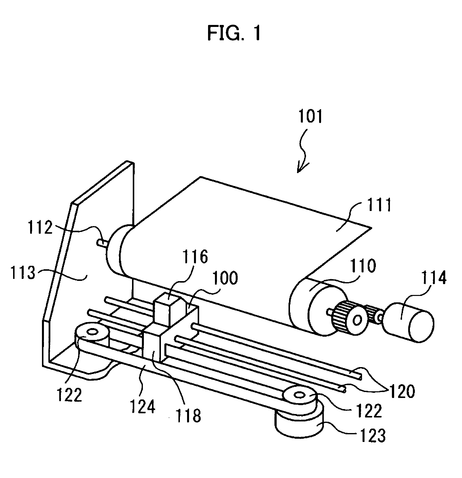
[0076]In the following, a first embodiment of the present invention will be explained with reference to the drawings. First, with reference to FIG. 1, an explanation will be given about a construction of an ink-jet printer 101 carrying an ink-jet head 100 as an example of a fluid transporting apparatus provided with a piezoelectric actuator. FIG. 1 is a perspective view of major portions of the ink-jet printer 101.

[0077]As shown in FIG. 1, the ink-jet printer 101 includes a platen roller 110 as a sheet transporting means to transport a sheet 111 as a recording objective, and a carriage 118 on which an ink-jet head 100 and an ink cartridge 116 to be filled with an ink are to be mounted. The ink-jet head 100 is arranged in the carriage 118 at a position facing the platen roller 110 to perform printing on the sheet 111. The platen roller 110 is rotatably attached to a frame 113 by a shaft 112, and is driven to rotate by a motor 114. The carriage 118 is slidably supported by two guide r...

second embodiment

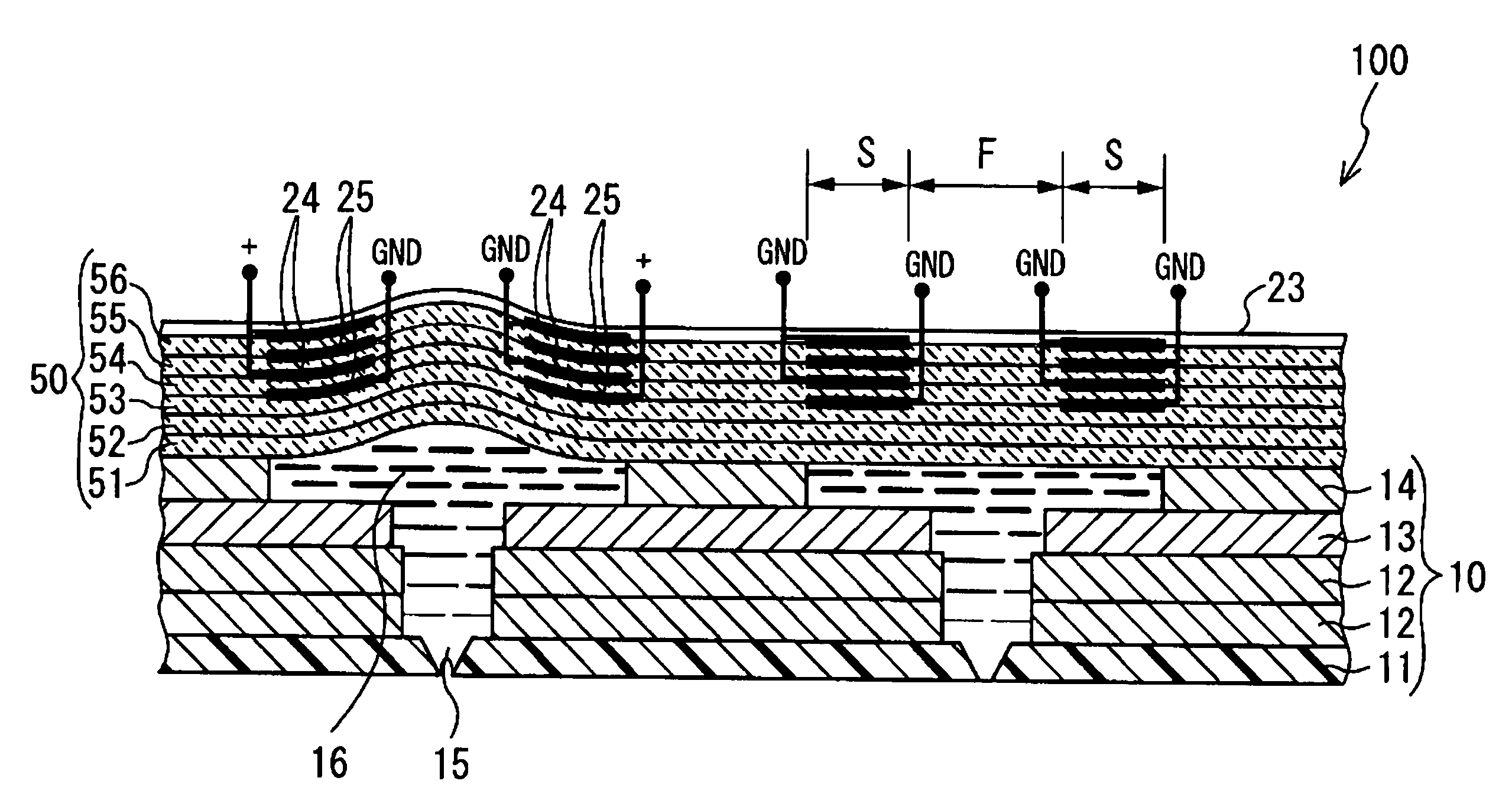
[0099]Next, an ink-jet head 100 including a piezoelectric actuator 50 according to a second embodiment will be explained with reference to FIG. 11. It should be noted that the ink-jet head 100 of this embodiment includes a cavity plate 10 with the same configuration as the cavity plate 10 of the first embodiment.

[0100]In the same manner as in the first embodiment, the piezoelectric actuator 50 has a first portion F and a pair of second portions S corresponding to each of the pressure chambers 16. In this embodiment, in the second portions S, electrodes 24, 25 are arranged between adjacent layers of the piezoelectric sheets 51 to 53 which are located close to the pressure chambers 16 in the thickness direction of the piezoelectric actuator. The common electrodes 25 are arranged between the adjacent layers of the piezoelectric sheets 51 to 53 in the direction in which the piezoelectric sheets are stacked, along the outer periphery of each of the pressure chambers 16. The drive electro...

third embodiment

[0103]Next, an ink-jet head 100 including a piezoelectric actuator 50 according to a third embodiment of the present invention will be explained with reference to FIG. 12. The piezoelectric actuator 50 of the present embodiment has a configuration similar to the piezoelectric actuator 50 of the first embodiment, except that a notch 57 is formed in the surface of each of the first portions F at a position shifted in the thickness direction of the piezoelectric actuator 50 in the direction in which the first portion F archingly deforms. In other words, the notch 57 is formed on the surface of each of the first portion F opposite to one of the pressure chambers 16. Further, a connection electrode 58 is formed, for example, by continuously depositing a conductive material on the inner surface of the notch 57 and on the surface of the piezoelectric actuator 50. A wiring which extends from either the drive electrodes 24 or the common electrodes 25 is connected to the connection electrode ...


PUM


Abstract

An ink-jet head 501 as a liquid transportation apparatus includes pressure chambers 514, and a piezoelectric layer 503 having individual electrodes 532 and a vibration plate 530. When W is a length in the radial direction of pressure chambers 514, and A is a length in the radial direction of portions of individual electrodes 532 to which a drive voltage is applied, the portions being formed at areas each overlapping with one side portion, in the radial direction, of the edge portion of one of the pressure chambers 514, the length A in the radial direction of individual electrodes 532 is determined based on a relationship between the value of A / (W / 2) and an amount of deformation of the vibration plate 530 when the drive voltage is applied to the individual electrode 532, such that the amount of the deformation of the vibration plate 530 becomes great. Accordingly, a liquid transporting apparatus provided with the piezoelectric actuator which has excellent durability and more improved drive efficiency.

Description

CROSS-REFERENCES TO RELATED APPLICATIONS[0001]This application is a Continuation-In-Part Application of U.S. application Ser. No. 10 / 310,750 filed on Dec. 5, 2002 now U.S. Pat. No. 6,971,738 claiming the priority of Japanese patent Applications No. 2001-372104 filed on Dec. 6, 2001; No. 2002-132195 filed on May 8, 2002; and No. 2002-284304 filed on Sep. 27, 2002.BACKGROUND OF THE INVENTION[0002]1. Field of the Invention[0003]The present invention relates to a liquid transporting apparatus which transport a liquid and a method for producing a liquid transporting apparatus.[0004]2. Description of Related Art[0005]As an example of conventional recording apparatus which performs recording on a recording medium such as paper, an ink-jet printer provided with an ink-jet head is known (for example, see Patent Document 1).[0006][Patent Document 1] Japanese Patent Publication No. 3128857[0007]As shown in FIG. 47, the ink-jet head 420 is constructed of a stack in which an actuator plate 421 d...

Claims


Application Information

Patent Timeline
Patent Type & Authority Patents(United States)
IPC IPC(8): B41J2/045
CPCB41J2/14209B41J2/14233B41J2/1609B41J2/161B41J2/1623B41J2/1626B41J2/1632B41J2/1642B41J2/1646B41J2002/14217B41J2002/14225B41J2002/14266B41J2002/14491
Inventor SUGAHARA, HIROTO
Owner BROTHER KOGYO KK
Why Eureka
Try Eureka