
Guide carriage of a linear rolling bearing

a technology of linear rolling bearings and bearings, which is applied in the direction of bearings, linear bearings, shafts and bearings, etc., can solve the problems of inability to pass lubricant, and achieve the effect of simple production

Active Publication Date: 2008-10-14
SCHAEFFLER TECH AG & CO KG
View PDF26 Cites 12 Cited by
  • Summary
  • Abstract
  • Description
  • Claims
  • Application Information

AI Technical Summary

Benefits of technology

[0005]At least one of the head pieces is preferably provided with the lubricant channel which can be connected to the deflection section via the valve, for supplying lubricant. Said head pieces which are also of multiple-part configuration are usually from plastic using the injection molding process. In this case, the valve can be formed integrally on the head piece or one of the parts of the head piece, it being possible for the slot to be taken into consideration without problems as early as during the injection molding process. The slot faces which delimit the slot are preferably pressed against one another elastically. This means that, outside of the relubrication intervals, the lubricant channel is closed when the slots are pressed against one another.
[0007]One refinement of the slot which is simple to produce in technical terms and is particularly favorable for the purpose of relubrication can consist in the fact that the funnel has slots in the shape of a cross, as viewed in the longitudinal direction of the lubricant channel. Accordingly, four funnel segments are formed which can be deflected elastically in each case, with the result that they open the cross slot. The slotted funnel is preferably manufactured from plastic, in particular using the injection molding process. If the funnel is arranged in the lubricant channel, the funnel segments can be formed integrally with their outer circumference on the wall of the lubricant channel, to be precise such that every segment can still be deflected elastically.
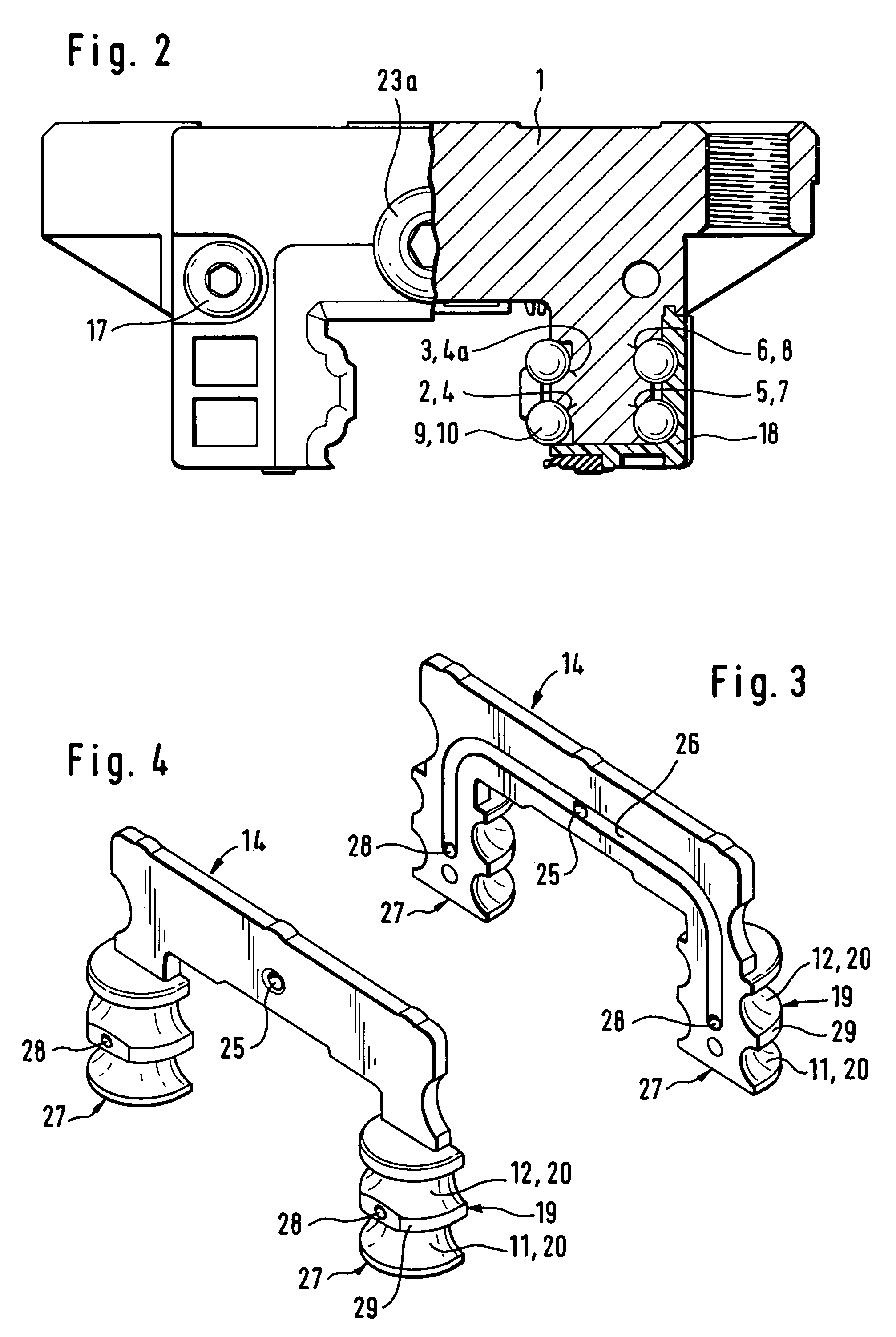
[0008]A further development according to the invention provides for the head piece to comprise a distributor plate which is formed from plastic and is provided with a branched distributor channel for the distribution of the lubricant, at the ends of which distributor channel transfer holes are provided, the slots being arranged in the transfer holes. The guide carriages are usually of approximately U-shaped configuration, as viewed in cross section. As viewed in cross section through the guide carriage, the distributor channel can begin, for example, centrally between the two limbs of the U-shaped profile and then be branched to both limbs of the guide carriage. The transfer holes end finally in the region of the deflection section, that is to say of the deflection channel. In this development according to the invention, it is also favorable if the funnel is formed integrally on the distributor plate. Furthermore, in order to reduce components, it is proposed that the deflection section has an inner deflection means, known per se, for the rolling bodies, the inner deflection means being configured integrally with the distributor plate. This means that a single component has the lubricant channel, the valve and also the inner deflection means. Parts of this type can be manufactured without problems from plastic using the injection molding process.
[0009]If the transfer hole opens at the inner deflection means, it is appropriate, according to a development according to the invention, for the inner deflection means to be provided with two adjacent ball grooves for in each case one endless raceway, the transfer holes then opening into a separating web which separates the two ball grooves. Firstly, this therefore ensures that the opening lies outside the raceway region of the rolling bodies and, secondly, this ensures that lubricant can pass equally into both ball grooves.

Problems solved by technology

It is not possible for lubricant to pass through the slot from the opposite side.

Method used


Image

  • Guide carriage of a linear rolling bearing
  • Guide carriage of a linear rolling bearing
  • Guide carriage of a linear rolling bearing

Examples


Embodiment Construction

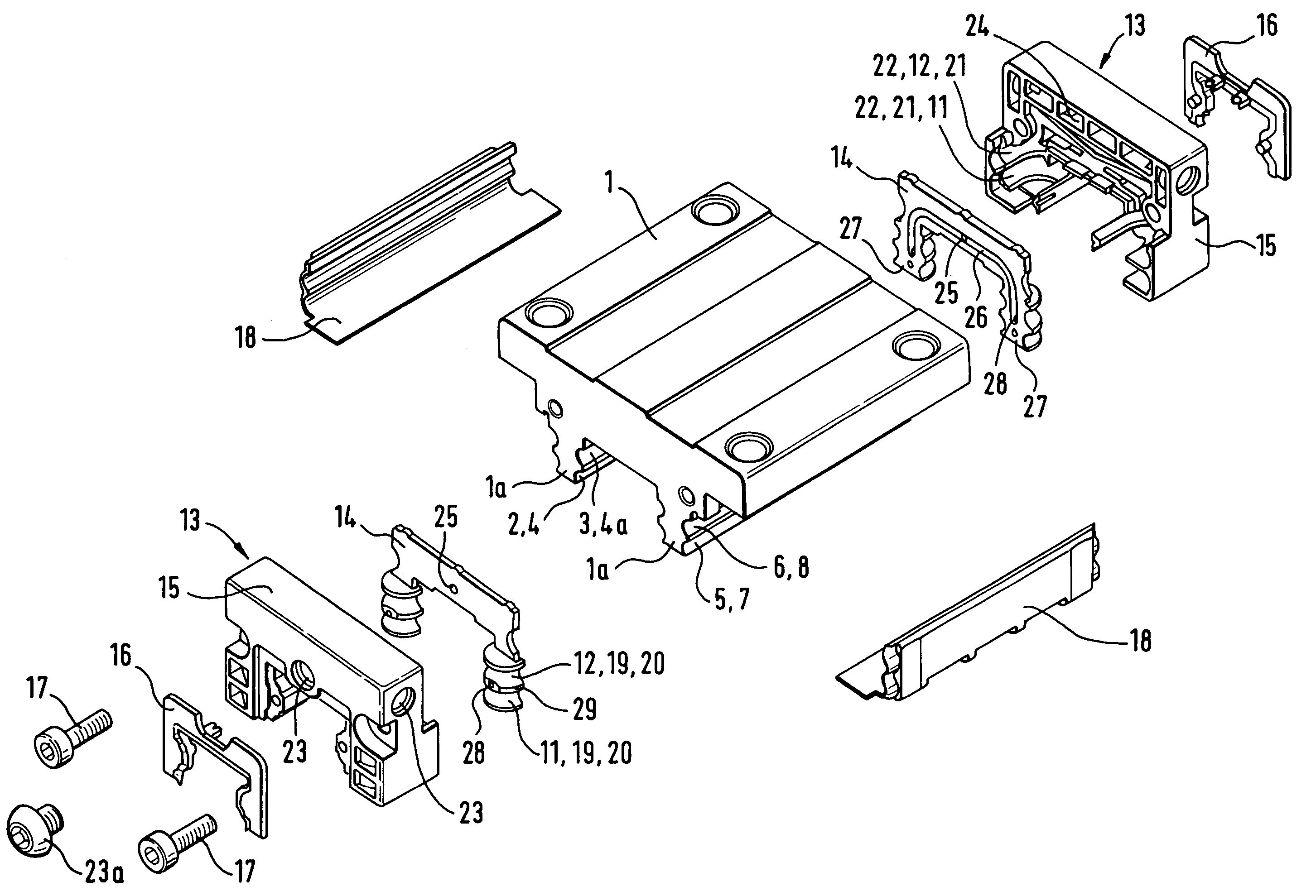
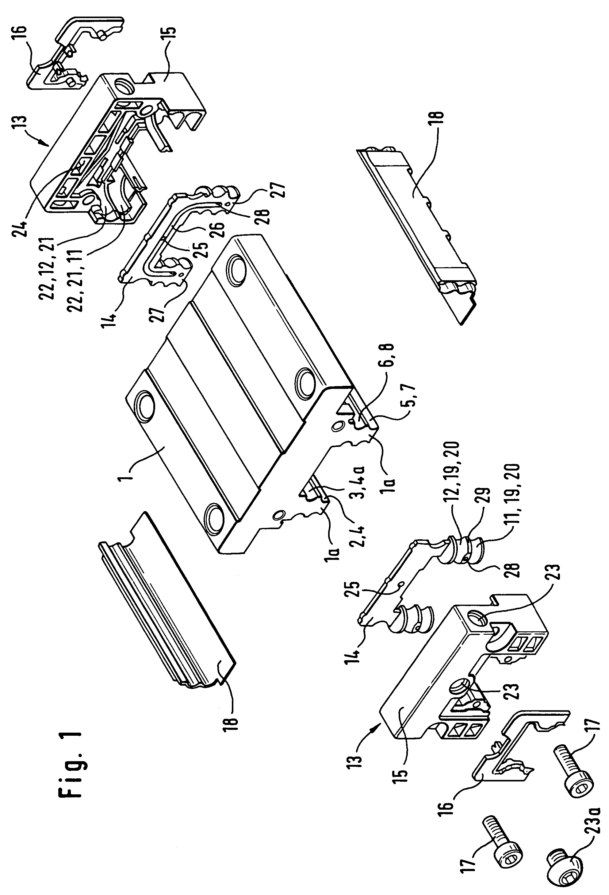
[0019]The guide carriage according to the invention from FIG. 1 comprises an approximately U-shaped carrying body 1, in each case two carrying sections 2, 3 which are configured as ball grooves 4, 5 in the present case being formed on the two limbs 1a of said carrying body 1, which limbs 1a are formed on the longitudinal sides. Furthermore, in each case two return sections 5, 6 which are likewise configured as ball grooves 7, 8 in the present case are formed on the two limbs 1a. Rolling bodies 9 which are shown in FIG. 2 and are configured here as balls 10 can roll under load on the carrying sections 2, 3. Said rolling bodies 9 can run back without load on the return sections 5, 6. The return sections 5, 6 and the carrying sections 2, 3 are connected endlessly to one another via deflection sections 11, 12, the deflection section 11 connecting the return section 5 endlessly to the carrying section 2 and the deflection section 12 connecting the return section 6 endlessly to the carryi...


PUM


Abstract

A guide carriage of a linear roller bearing, having at least one endless raceway for rolling bodies (9), and having a carrying body (1), on the two longitudinal sides of which in each case one carrying section (2, 3) and one return section (5, 6) of the endless raceway is provided, the carrying section (2, 3) being provided rolling bodies (9) which roll under load and the return section (5, 6) being provided for rolling bodies (9) which return without load, and having head pieces (13) which are arranged on end sides of the carrying body (1) and in each case have one deflection section (11, 12) which connects the return section (5, 6) to the carrying section (5, 6) a lubricant channel (24) being provided for the supply of lubricant, which lubricant channel (24) can be connected to the raceway of the rolling body (9) via a valve (30), the valve (30) having a slot (33) which is provide for the passage of lubricant, crosses the cross section of the lubricant channel (24) and is delimited by slot faces (34), the slot faces (34) bearing against one another when the valve (30) is shut, with the slot (33) being closed.

Description

[0001]This application is a 371 of PCT EP 2004 / 006753 filed Jun. 23, 2004.[0002]The present invention relates to a guide carriage of a linear roller bearing. Guide carriages of this type are often provided with one or more lubricant channels, in order to take lubricant to the desired lubricating points of the linear roller bearing.BACKGROUND OF THE INVENTION[0003]For example, DE 42 10 299 A1 has disclosed a guide carriage according to the features of the precharacterizing clause of claim 1. A lubricating nipple is arranged on the head piece, which lubricating nipple is connected to a lubricant channel. The lubricant channel ends at the inner deflection means of the head piece in the region of the deflection section. Sealing lips are configured on the head piece at this end of the lubricant channel, which sealing lips bear against the end side of the carrying body and close the end of the lubricant channel. In this way, it is ensured first of all that lubricant which is arranged in t...

Claims


Application Information

Patent Timeline
IPC IPC(8): F16C29/06F16C33/10F16C33/66
CPCF16C29/0661F16C33/6622F16C33/6681F16C29/0609F16C33/6629
Inventor NEUFANG, LOTHARKELLER, PETER
Owner SCHAEFFLER TECH AG & CO KG
Learn More