Rotatable video connector for cables and adapters
a video connector and rotatable technology, applied in the direction of current collectors, coupling device connections, coupling device details, etc., can solve the problems of inability to use conventional cables, limited range, and blockage of two directions, so as to facilitate the installation of the connector
- Summary
- Abstract
- Description
- Claims
- Application Information
AI Technical Summary
Benefits of technology
Problems solved by technology
Method used
Image

Examples
Embodiment Construction
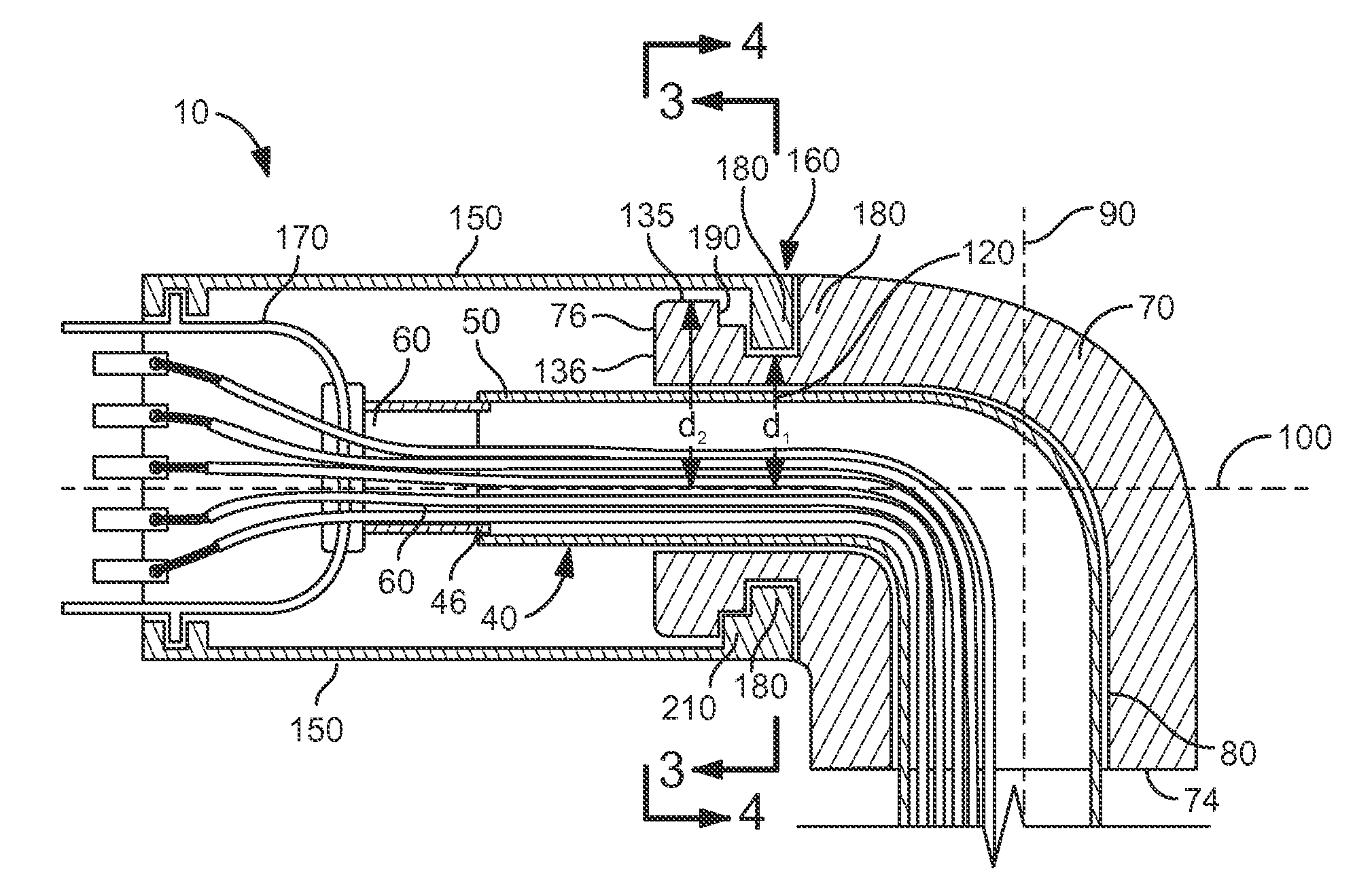
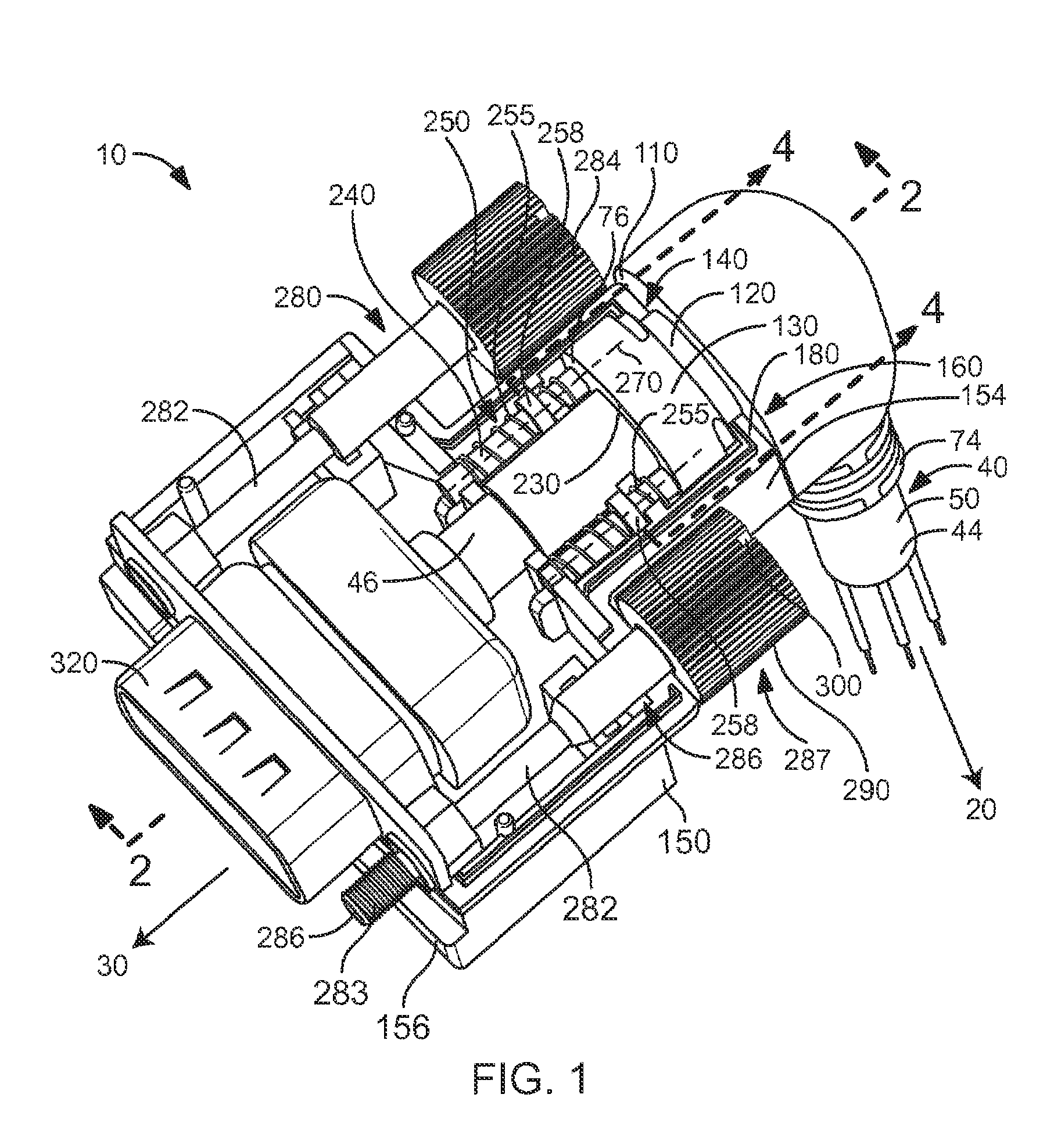
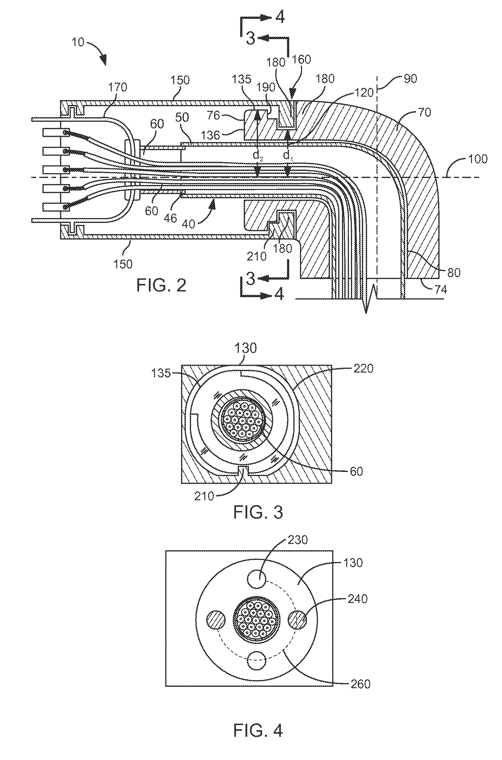
[0027]The present invention is an electrical connector 10 for conducting an electrical signal from a source 20 to a destination 30. The source 20 may be a video output device (not shown), for example, and the destination 30 may be a video display device (not shown).
[0028]The electrical connector 10 includes a cable 40 that has an outer electrically insulating sheath 50 and contains at least one insulated electrical conductor 60. The cable 40 has a distal end 44 and a proximal end 46. The cable 40 may include as many as 36 electrical conductors 60 when, for example, the electrical signal is a video signal. However, other numbers of conductors 60 may be included within the cable 40 for other types of signals, as is known in the art.
[0029]The electrical connector 10 further includes a substantially L-shaped plug 70 that has a conduit 80 therethrough for conveying the at least one electrical conductor 60 of the cable 40 therethrough. The L-shaped plug 70 further includes a distal end 74...
PUM
 Abstract
Description
Claims
Application Information
 - Generate Ideas
- Intellectual Property
- Life Sciences
- Materials
- Tech Scout
- Unparalleled Data Quality
- Higher Quality Content
- 60% Fewer Hallucinations
Browse by: Latest US Patents, China's latest patents, Technical Efficacy Thesaurus, Application Domain, Technology Topic, Popular Technical Reports.
© 2025 PatSnap. All rights reserved.Legal|Privacy policy|Modern Slavery Act Transparency Statement|Sitemap|About US| Contact US: help@patsnap.com