Electrical connector with improved contact arrangement

a technology of contact arrangement and electric connector, which is applied in the direction of connection contact member material, coupling protective earth/shielding arrangement, and connection device connection, etc., can solve the problems of signal transmission delay between such signal contacts, and achieve balanced signal transmission, excellent high-frequency characteristics, and low cross talk

Inactive Publication Date: 2008-10-14
HON HAI PRECISION IND CO LTD
View PDF11 Cites 25 Cited by
  • Summary
  • Abstract
  • Description
  • Claims
  • Application Information

AI Technical Summary

Benefits of technology

[0006]Accordingly, an object of the present invention is to provide an electrical connector that has excellent high-frequency characteristics and can provide balanced signal transmission and low cross talk.

Problems solved by technology

In this condition, there is a signal transmission delay between such signal contacts.

Method used


Image

  • Electrical connector with improved contact arrangement
  • Electrical connector with improved contact arrangement
  • Electrical connector with improved contact arrangement

Examples


Embodiment Construction

[0017]Reference will now be made in detail to the preferred embodiment of the present invention.

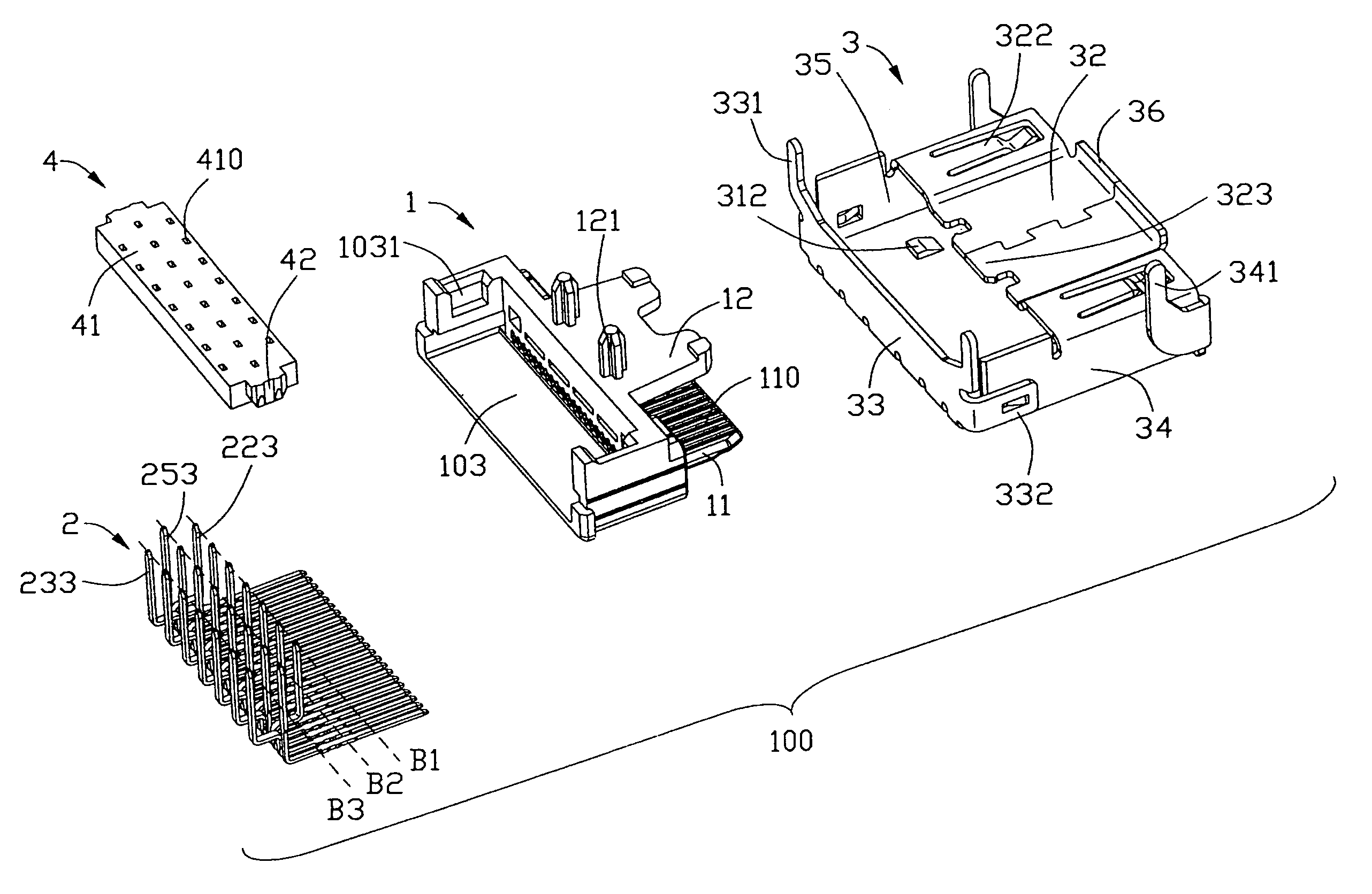
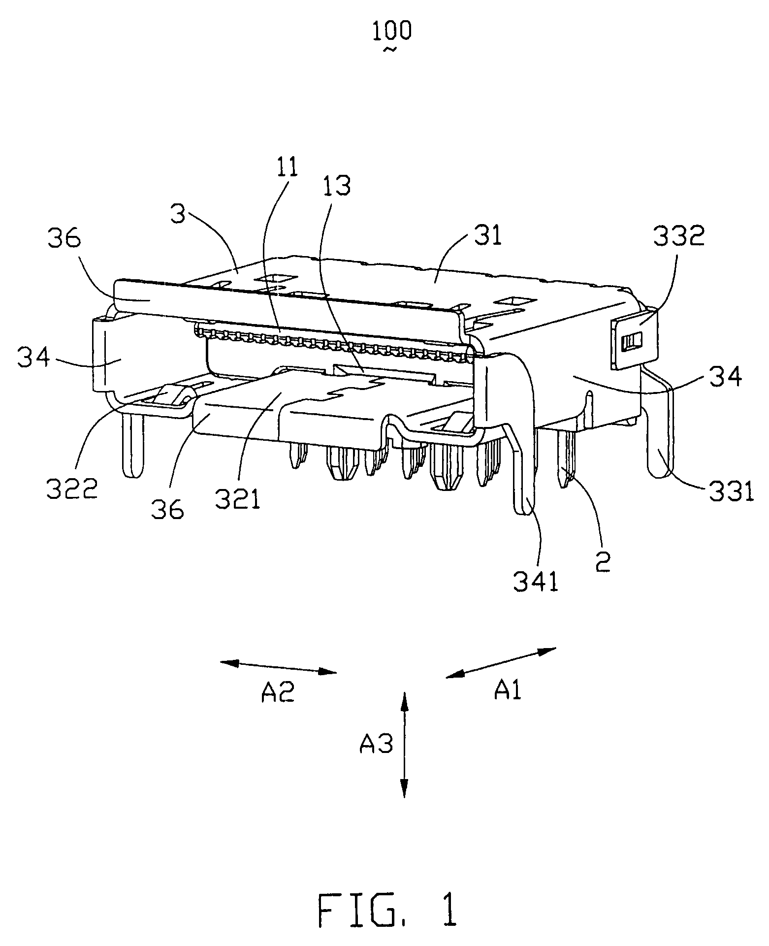
[0018]Referring to the drawings and in particular to FIGS. 1 to 5, an electrical connector 100 having a first end for fitting with a mating connector (not shown) and a second end for connecting to a printed circuit board (PCB, not shown). The electrical connector 100 is connected to the mating connector in a first direction A1 in order to transmit a balanced signal. The connector 100 is mounted on the PCB in a third direction A3 perpendicular to the first direction A1. A direction perpendicular to the first and third directions A1, A3 will be called a second direction A2.

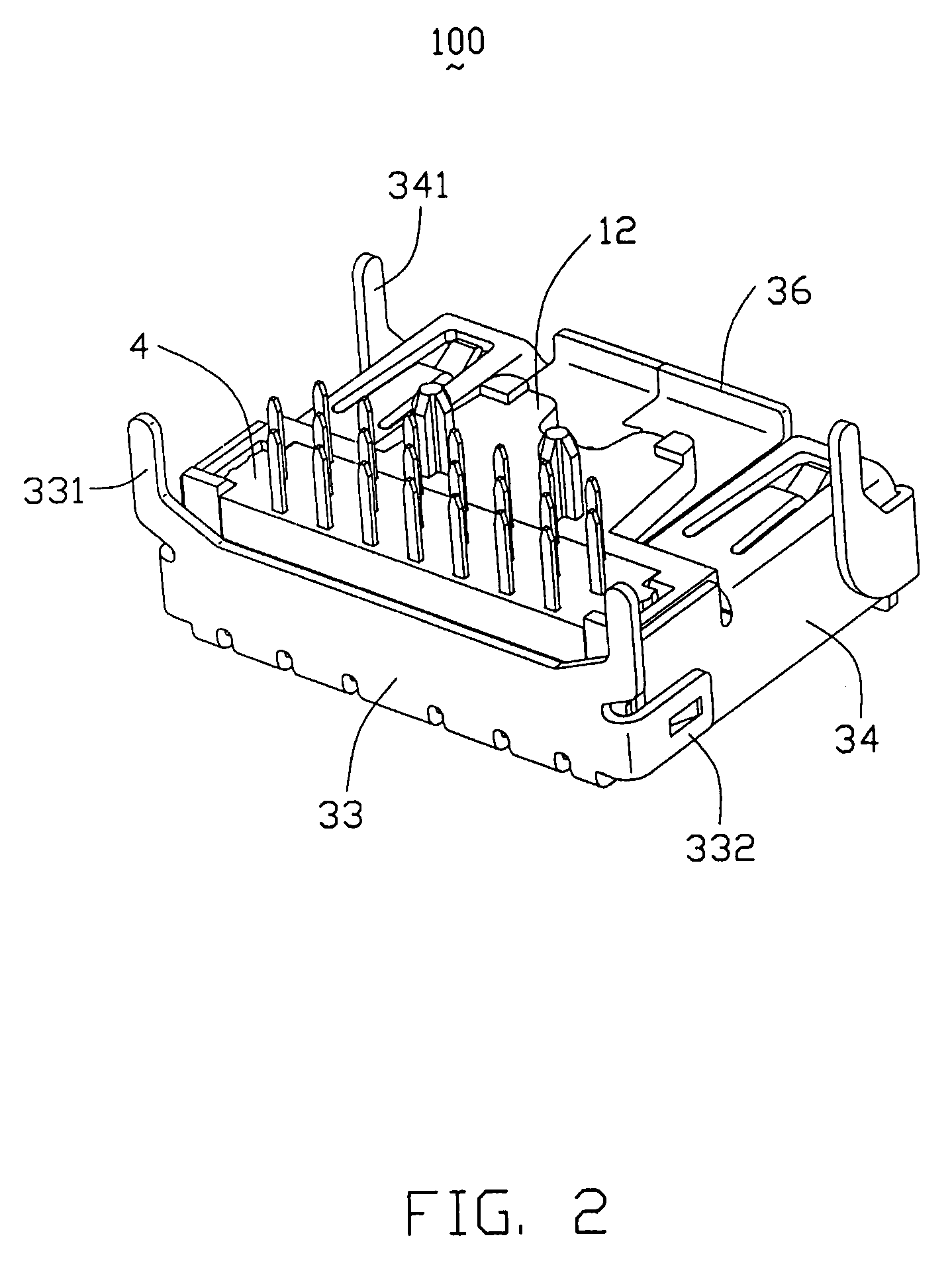
[0019]The electrical connector 100 comprises an insulative housing 1, a plurality of contacts 2 retained in the insulative housing 1, a metal shield 3 enclosing the housing 1 and a spacer 4 for mating with the contacts 2.

[0020]The insulative housing 1 includes a base 10, a tongue plate 11 and a bottom plate 12. The base 1...


PUM


Abstract

An electrical connector (100) has a first end for fitting with another connector and a second end for connecting to a board. The connector comprises an insulative housing (1), a number of contacts (2) and a metal shield (3) enclosing the insulative housing. The insulative housing includes a tongue plate (11) with a number of passageways (110) defined therein for receiving the contacts. The contacts are arranged side by side in the first end and arranged in three parallel rows in the second end. The contacts include signal contact pairs (21) and grounding contacts (22) disposed adjacent to and separating the signal contact pairs. Each signal contact pair includes a first signal contact and a second signal contact being substantially in equal length of the first signal contact. The signal contact pairs have matched impedance for transmitting high-speed signals, thereby canceling any cross talk therebetween.

Description

BACKGROUND OF THE INVENTION[0001]1. Field of the Invention[0002]This invention generally relates to an electrical connector, and more particularly to an electrical connector with improved contact arrangement to provide balanced signal transmission and low cross talk.[0003]2. Description of the Prior Art[0004]Electronic devices that operate, in part, to send electronic signals and to receive electronic signals communicate with one another. New electronic devices continue to be developed, which transmit the signals at ever increasing speed, and which devices simultaneously process increased numbers of simultaneously occurring signals. Accordingly, a trend that electrical connectors mounted in such devices need improved contact arrangement for transmitting high-frequency signals comes into being. U.S. Pat. No. 6,986,681 B2, discloses a conventional electrical connector which includes an insulative housing and a plurality of contacts retained in the insulative housing. The contacts incl...

Claims


Application Information

Patent Timeline
Patent Type & Authority Patents(United States)
IPC IPC(8): H01R13/648
CPCH01R12/58H01R12/716H01R13/65802H01R13/6582
Inventor XIAO, XUE-YUANZHANG, GUO-HUAHU, JIN-KUI
Owner HON HAI PRECISION IND CO LTD
Why Eureka
Try Eureka