
Non-surgical correcting abnormal knee loading

a knee joint and loading technology, applied in the field of knee braces, can solve the problems of affecting the normal functioning of the knee joint, so as to minimize the likelihood of osteoarthritis and/or osteoarthritis symptoms, and the hinge length is variable.

Inactive Publication Date: 2008-10-14
UNIV OF COLORADO THE REGENTS OF
View PDF59 Cites 26 Cited by
  • Summary
  • Abstract
  • Description
  • Claims
  • Application Information

AI Technical Summary

Benefits of technology

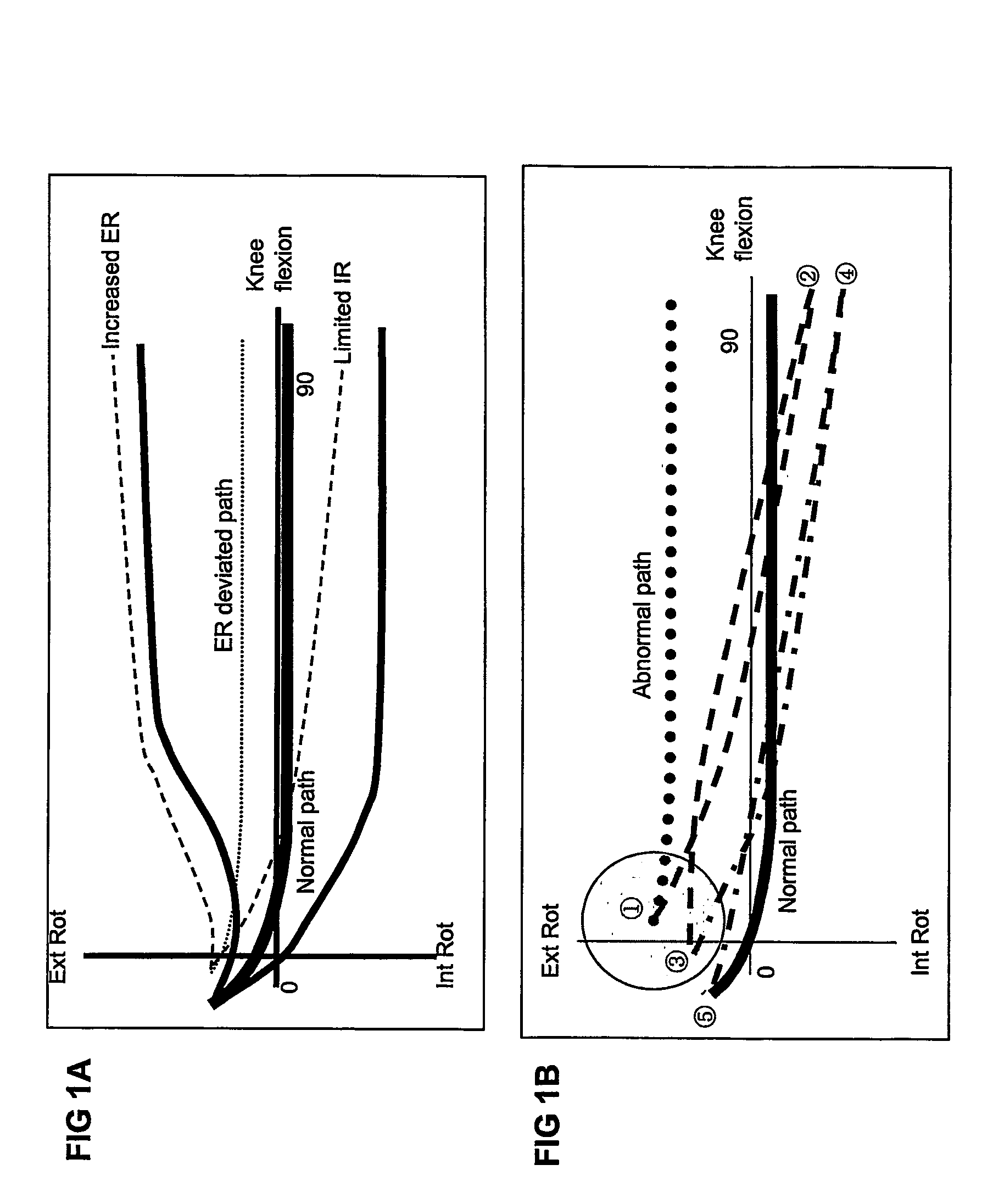
[0008]The present invention reduces the effects of OA and abnormal loading of the knee by applying a force to correct tibial translational and rotational malalignment. Accordingly, the present invention provides a method of reducing abnormal rotational alignment by applying a torsional force to correct abnormal rotational alignment during flexion.
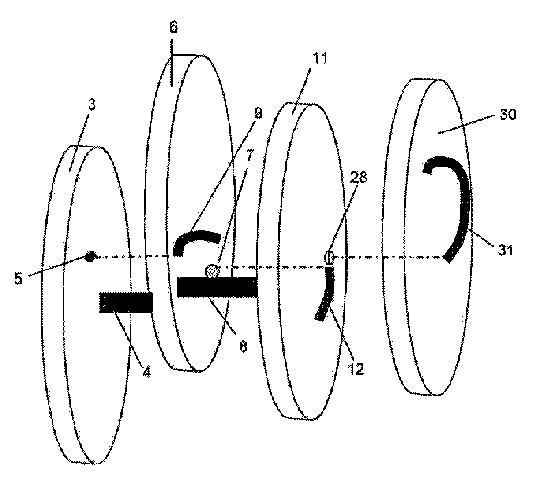
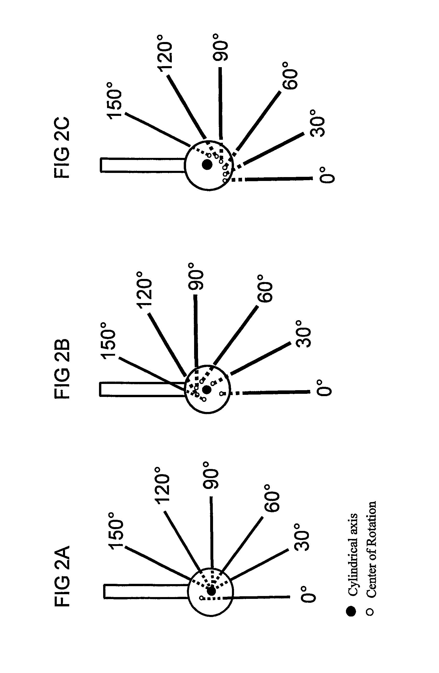
[0022]The present invention also provides methods for treating knee pathology, including an osteoarthritic or osteoarthritic-prone knee. The method comprises application of a rotational force to the tibia during flexion to correct the abnormal tibial rotation by a pair of hinges. The hinges have a variable hinge length, dependent on flexion, and are located medial and lateral to the knee, such that an off-loading force can also be applied to the knee. Application of both forces during repeated flexion / extension cycles can correct abnormal knee rotation and can minimize the likelihood of osteoarthritis and / or osteoarthritic symptoms. These forces can be generated by paired hinges of the present invention, wherein the center of rotation of each hinge varies as a function of flexion. In addition, use of multiple shell slots and shell protuberances to track each of the shell slots permits the center of rotation location to vary as a function of flexion, wherein the function can be different for a first flexion range (tracking of a middle shell protuberance with an outer shell slot) and a second flexion range (tracking of an inner shell protuberance with a middle shell slot). The medial and lateral hinges can each also have a different center of rotation location as a function of flexion. Any of the hinges or braces of the invention can also be used for treating an injured or injury-prone knee.

Problems solved by technology

Because the knee joint is used so often, and is one of the most mobile and flexible joints in the body, it is vulnerable to injury.
Malalignment of the knee joint can occur when any of the tendons or ligaments is damaged.
Malalignment of the tibia causes abnormal loading of forces across the knee, disrupts the normal knee joint motion, and osteoarthritis (OA) of the knee.
However, many prior art knee braces apply a unilateral varus force on the valgus knee or valgus force on the varus knee to relieve pressure on the side of the knee that is injured when the leg is fully extended (see U.S. Pat. No. 5,277,698).
These off-loading braces, therefore, are relatively bulky, heavy, and tend to slide down the leg.
These braces do not, however, compensate for the rotational malalignment of the tibia.
When the leg is fully extended, however, accessory movement of the knee is restricted (the tibia cannot rotate).
Thus, any force applied to the fully extended leg is not effective in correcting the underlying rotational malalignment of the tibia.
Most braces do not properly simulate the complex three-dimensional motion of the knee joint.
Other braces only permit limited motion of the knee joint without providing for the more complicated multi-dimensional motion of the joint.
Another type of brace hinge has linking and pivot members wherein the pivot point changes during rotational movement (U.S. Pat. No. 5,230,697), but does not control other motions.
Still other braces that attempt to control knee motion in three-dimensions are bulky.

Method used


Image

  • Non-surgical correcting abnormal knee loading
  • Non-surgical correcting abnormal knee loading
  • Non-surgical correcting abnormal knee loading

Examples


Embodiment Construction

[0033]All references cited herein are hereby incorporated by reference to the extent not inconsistent with the disclosure herewith. As used herein, “comprising” is synonymous with “including,”“containing,” or “characterized by,” and is inclusive or open-ended and does not exclude additional, unrecited elements or method steps. As used herein, “consisting of” excludes any element, step, or ingredient not specified in the claim element. As used herein, “consisting essentially of” does not exclude materials or steps that do not materially affect the basic and novel characteristics of the claim. Any recitation herein of the term “comprising”, particularly in a description of components of a composition or in a description of elements of a device, is understood to encompass those compositions and methods consisting essentially of and consisting of the recited components or elements. The invention illustratively described herein suitably may be practiced in the absence of any element or e...


PUM


Abstract

The invention provides hinges for use in knee braces to correct and prevent knee pathology. Further provided are knee braces comprising the hinges of the present invention to correct and prevent knee pathology including osteoarthritis. Also provided are methods of treating knee pathology by using the hinges and braces of the present invention to apply a corrective rotational force and an off-loading force to the affected knee compartment.

Description

CROSS-REFERENCE TO RELATED APPLICATIONS[0001]This application is a national stage application under 35 U.S.C. §371 of PCT / US04 / 41304, filed Dec. 10, 2004, which takes priority from U.S. Provisional patent application nos. 60 / 529,139 filed Dec. 12, 2003 and 60 / 543,515 filed Feb. 10, 2004, all of which are incorporated by reference in their entirety herein.FIELD OF INVENTION[0002]The invention relates to correction and prevention of osteoarthritis in knees and more specifically knee braces, hinges used in knee braces and methods to prevent osteoarthritis and correct abnormal knee alignment.BACKGROUND OF THE INVENTION[0003]The knee is composed of three bones, the patella (knee cap), the femur and the tibia. The meniscus (cartilage), composed of the lateral and medial menisci, cushion and distribute the weight of the femur uniformly across the joint. The gaps between the tibia and femur on the inside and outside of the knee are called the “medial” and “lateral” compartments, respectivel...

Claims


Application Information

Patent Timeline
Patent Type & Authority Patents(United States)
IPC IPC(8): A61F5/00A61F
CPCA61F5/0123A61F2005/0146
Inventor GAMADA, KAZUYOSHI
Owner UNIV OF COLORADO THE REGENTS OF
Learn More