Modular long bone prosthesis for partial or total bone replacement

a technology of partial or total bone replacement and modularity, applied in the field of orthopedic prosthesis, can solve the problems of difficult and difficult to replace long bones so easily by prosthesis, etc., to achieve the effect of facilitating rotational alignment of the proximal componen

Active Publication Date: 2008-10-14
DEPUY PROD INC
View PDF24 Cites 65 Cited by
  • Summary
  • Abstract
  • Description
  • Claims
  • Application Information

AI Technical Summary

Benefits of technology

[0009]According to one aspect of the disclosure, a modular long bone prosthesis is provided having a proximal component and a retroversion component. The proximal component is configured at a proximal end to receive a head forming a portion of a joint and is formed at a distal end to mate with additional prosthesis components. The proximal component is formed to simulate an angle inherent in the proximal end of the bone to be replaced and includes an indicator adjacent the distal end to facilitate rotational alignment of the proximal component and additional prosthesis components. The retroversion component includes a proximal end configured to mate with the distal end of the proximal component. The proximal end includes alignment indicia for positioning relative to the indicator on the proximal component. When the indicator is in a first position relative to the alignment indicia the proximal component and the retroversion component establish a first alignment orientation forming an angle simulating the angle inherent in the proximal end of the right long bone of the long bone to be replaced. When the indicator is in a second position relative to the alignment indicia the proximal component and the retroversion component establish a second alignment orientation forming an angle simulating the angle inherent in the proximal end of the left long bone of the long bone to be replaced.

Problems solved by technology

While many devices exists for the replacement of a damaged or defective joint, the substitution of a bone, and particularly a long bone, is much more problematic.
While prosthetic phalanges have enjoyed increasing success, the long bones have not been so easily replaced by prosthesis, particularly to maintain the functionality of the patient's limb.
Perhaps the greatest difficulty is the extreme load-bearing nature of the long bones.
A further problem associated with a long bone prosthesis is the variability in length of a particular long bone between patients.
Yet an additional problem with total long bone prosthesis is that it is difficult to provide a prosthesis of the appropriate length prior to surgery because it is difficult to obtain an accurate pre-surgical measurement of the long bone.
Inaccurate measurement of the long bone prosthesis of course leads to an improper length of the extremity.
This mal-adjusted length can cause motor and muscular difficulties.
Moreover, an incorrect prosthesis length can affect the tightness of the tissue surrounding the prosthesis.
If the length is too short, the surrounding tissue is unnecessarily loose.
If the prosthesis is too long, the tissue may be too tight, if the prosthesis can be implanted at all.
While the prior prosthetic devices have gone a long way toward helping patients with bone or joint disorders, several needs remain unmet.

Method used


Image

  • Modular long bone prosthesis for partial or total bone replacement
  • Modular long bone prosthesis for partial or total bone replacement
  • Modular long bone prosthesis for partial or total bone replacement

Examples


Embodiment Construction

[0031]For the purposes of promoting an understanding of the principles of the invention, reference will now be made to the embodiments illustrated in the drawings and described in the following written specification. It is understood that no limitation to the scope of the invention is thereby intended. It is further understood that the present invention includes any alterations and modifications to the illustrated embodiments and includes further applications of the principles of the invention as would normally occur to one skilled in the art to which this invention pertains.

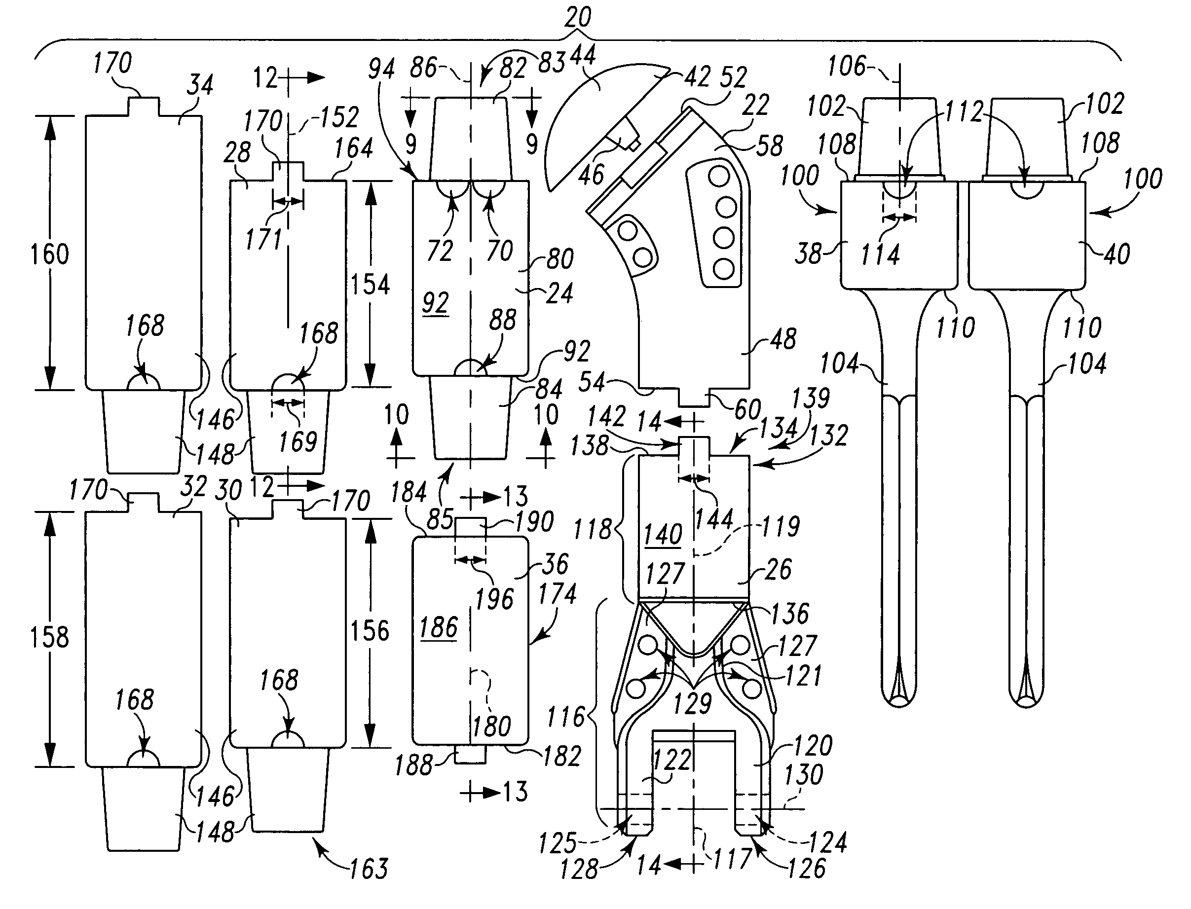
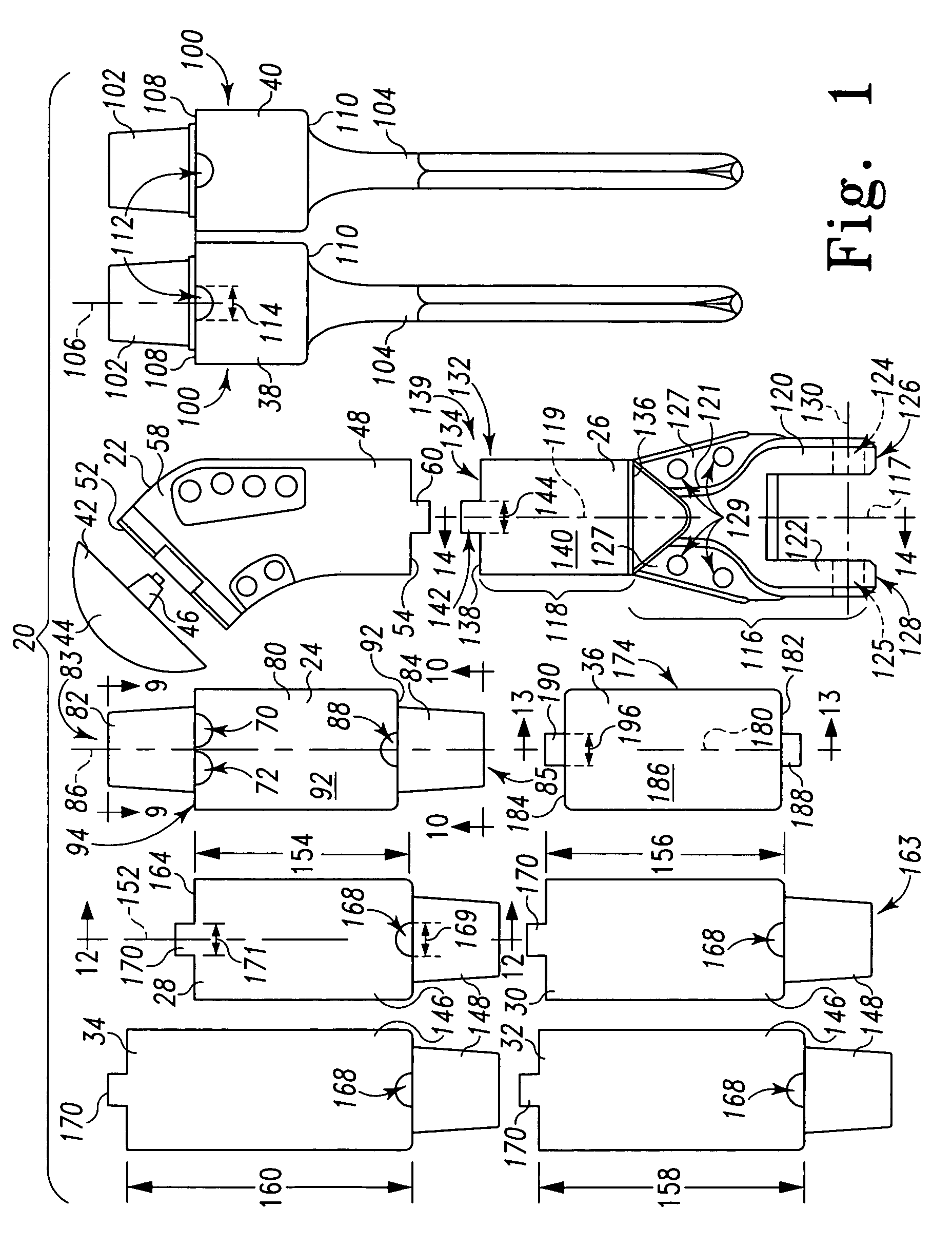
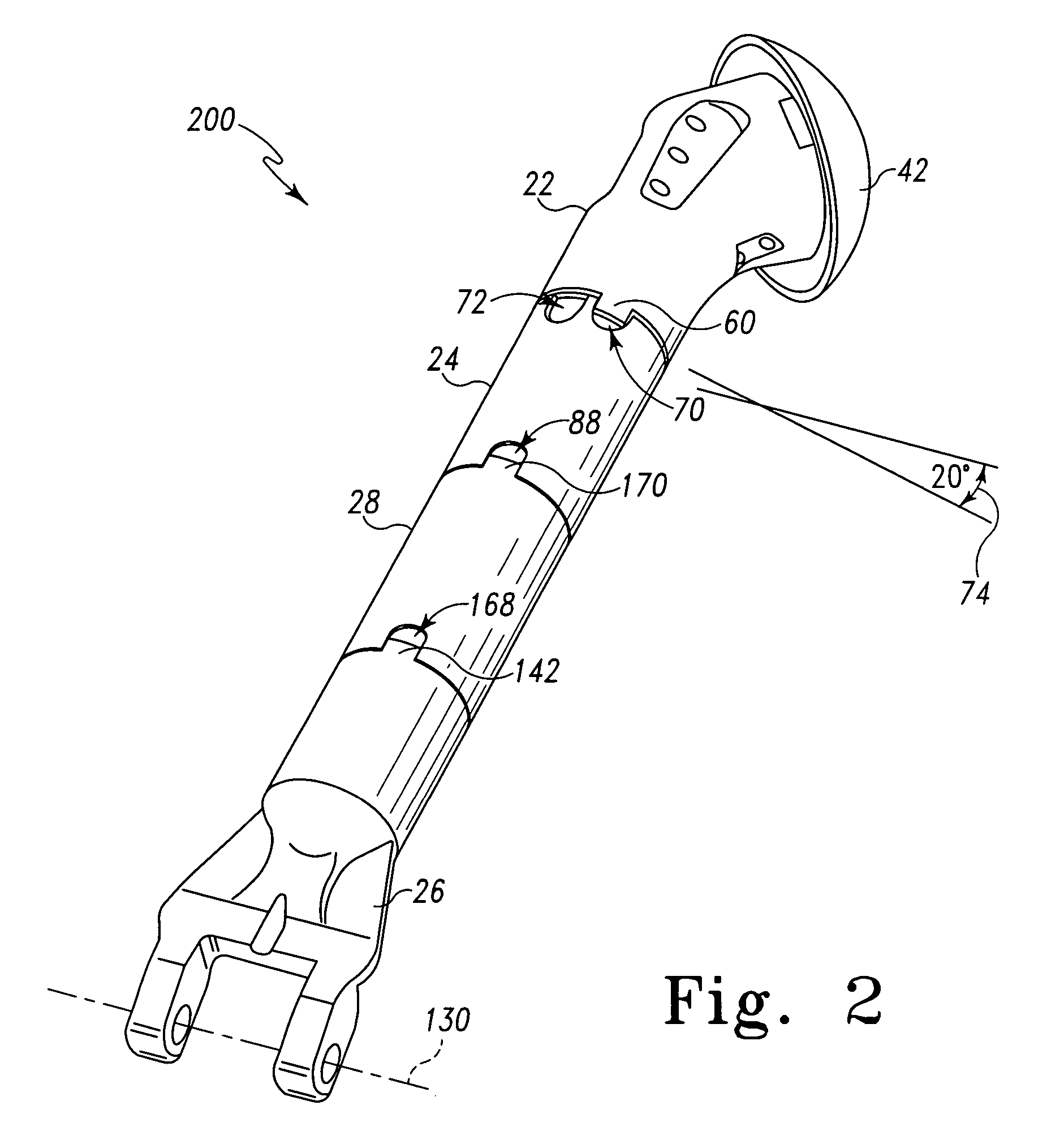
[0032]The disclosure contemplates a modular long bone prosthesis system or kit 20 that permits components to be assembled to act as a right long bone total replacement 200 (FIG. 2), a left long bone total replacement 300 (FIG. 3), a proximal long bone replacement 400 (FIG. 4), a distal long bone replacement 500 (FIG. 5) or an intercalary replacement 600 (FIG. 6). Each of the configurations of the prosthesis is a...


PUM


Abstract

A modular long bone prosthesis is provided having a proximal component and a retroversion component. The proximal component is configured at a proximal end to receive a head forming a portion of a joint and is formed at a distal end to mate with additional prosthesis components. The proximal component is formed to simulate an angle inherent in the proximal end of the bone to be replaced and includes an indicator adjacent the distal end to facilitate rotational alignment of the proximal component and additional prosthesis components. The retroversion component includes a proximal end configured to mate with the distal end of the proximal component. The proximal end includes alignment indicia for positioning relative to the indicator on the proximal component. When the indicator is in a first position relative to the alignment indicia the proximal component and the retroversion component establish a first alignment orientation forming an angle simulating the angle inherent in the proximal end of the right long bone of the long bone to be replaced. When the indicator is in a second position relative to the alignment indicia the proximal component and the retroversion component establish a second alignment orientation forming an angle simulating the angle inherent in the proximal end of the left long bone of the long bone to be replaced.

Description

BACKGROUND AND SUMMARY[0001]The present invention relates to an orthopedic prosthesis. More specifically, the invention concerns prosthesis for restoring the functionality of an extremity, such as an arm of a patient. The invention is particularly suited for the replacement of all or any part of a right or left long bone of the patient.[0002]The later half of the 20th century has seen a proliferation in the number of human skeletal components that can be replaced by a man-made prosthesis. Over the years these prosthesis have evolved from simply a physical substitution for a bone or a joint, to the more sophisticated fully functional prosthesis. For example, prostheses are well known for the replacement of the shoulder joint or the elbow joint. A modular shoulder prosthesis designed according to U.S. Pat. No. 5,314,479, assigned to DePuy, Inc., can be integrated into the existing glenoid cavity of a patient's shoulder. The prosthesis includes a lower stem that is configured to be emb...

Claims


Application Information

Patent Timeline
Patent Type & Authority Patents(United States)
IPC IPC(8): A61F2/40A61F2/32A61F2/00A61F2/28A61F2/30A61F2/36A61F2/38
CPCA61F2/28A61F2/3804A61F2/40A61F2/3607A61F2002/2853A61F2002/30224A61F2002/30332A61F2002/30341A61F2002/30342A61F2002/30344A61F2002/30382A61F2002/3054A61F2002/30551A61F2002/30599A61F2002/30604A61F2002/30607A61F2002/30616A61F2002/30617A61F2002/30626A61F2002/30708A61F2002/30785A61F2002/3082A61F2002/30878A61F2002/3822A61F2002/4011A61F2002/4018A61F2002/4029A61F2002/4051A61F2002/4062A61F2220/0033A61F2230/0069A61F2250/0062A61F2250/0063A61F2250/0084A61F2250/0097A61F2002/30339A61F2002/3055A61F2002/30331A61F2002/30624
Inventor BARNETT, GARY D.BROWN, SCOTT C.LESTER, MARK B.
Owner DEPUY PROD INC
Why Eureka
Try Eureka