Recessed electrical box

a technology of electrical boxes and outlet boxes, which is applied in the direction of electrical apparatus casings/cabinets/drawers, machine supports, coupling device connections, etc., to achieve the effect of reducing the cost of production of outlet boxes, and reducing the size of the box

Active Publication Date: 2008-10-14
ARLINGTON INDS
View PDF26 Cites 19 Cited by
  • Summary
  • Abstract
  • Description
  • Claims
  • Application Information

AI Technical Summary

Benefits of technology

[0008]A first advantage of the recessed electrical box is that it properly recesses or positions the box at the proper depth with respect to the outer surface of the building. The electrical box may include one or more outward extending flanges that provide a positioning mechanism to recess the electrical box at the correct depth within the building's surface. The positioning mechanism is functional for both a retrofit situation, in which the finished layer such as siding or stucco is installed, or in a building under construction in which the finished layer has not been installed.
[0009]A second advantage is that a while-in-use cover member, which renders the recessed electrical box rainproof, is minimal in size with respect to the box. Cover members are typically molded of expensive impact resistant plastic to meet electrical code. Keeping the cover minimal in size with respect to the box lowers the cost of production of the outlet box.
[0010]A further advantage is that the recessed electrical box positions an enclosed electrical device substantially behind the outer surface of the building. This provides added protection to the electrical device and insures that any hard impacts that destroy the cover member do not also damage the electrical device.
[0011]The recessed electrical box furthermore provides the advantage of being constructed of a minimal number of parts. It includes only two separately molded pieces, including the electrical box and the cover member. Construction of the box is therefore simplified and production costs are minimized as compared to similar prior art electrical boxes.
[0012]A further advantage of the recessed electrical box is that the cover member is a while-in-use cover, allowing electrical cords to remain connected to the electrical outlet within the box with the cover member closed thereon. Therefore the recessed electrical box provides rainproof protection to the outlets even while electrical cords are connected to the electrical outlets therein.
[0013]The electrical box furthermore includes integral bosses with bores therein, which may be smooth or threaded bores, for accepting fasteners from standard wall-mounted electrical devices, such as outlets or switches.

Problems solved by technology

Cover members are typically molded of expensive impact resistant plastic to meet electrical code.

Method used


Image

  • Recessed electrical box
  • Recessed electrical box
  • Recessed electrical box

Examples


first embodiment

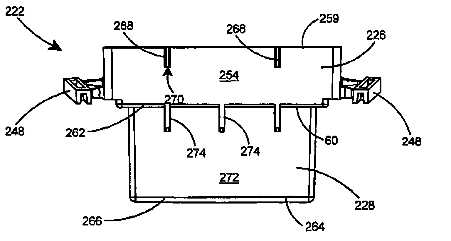
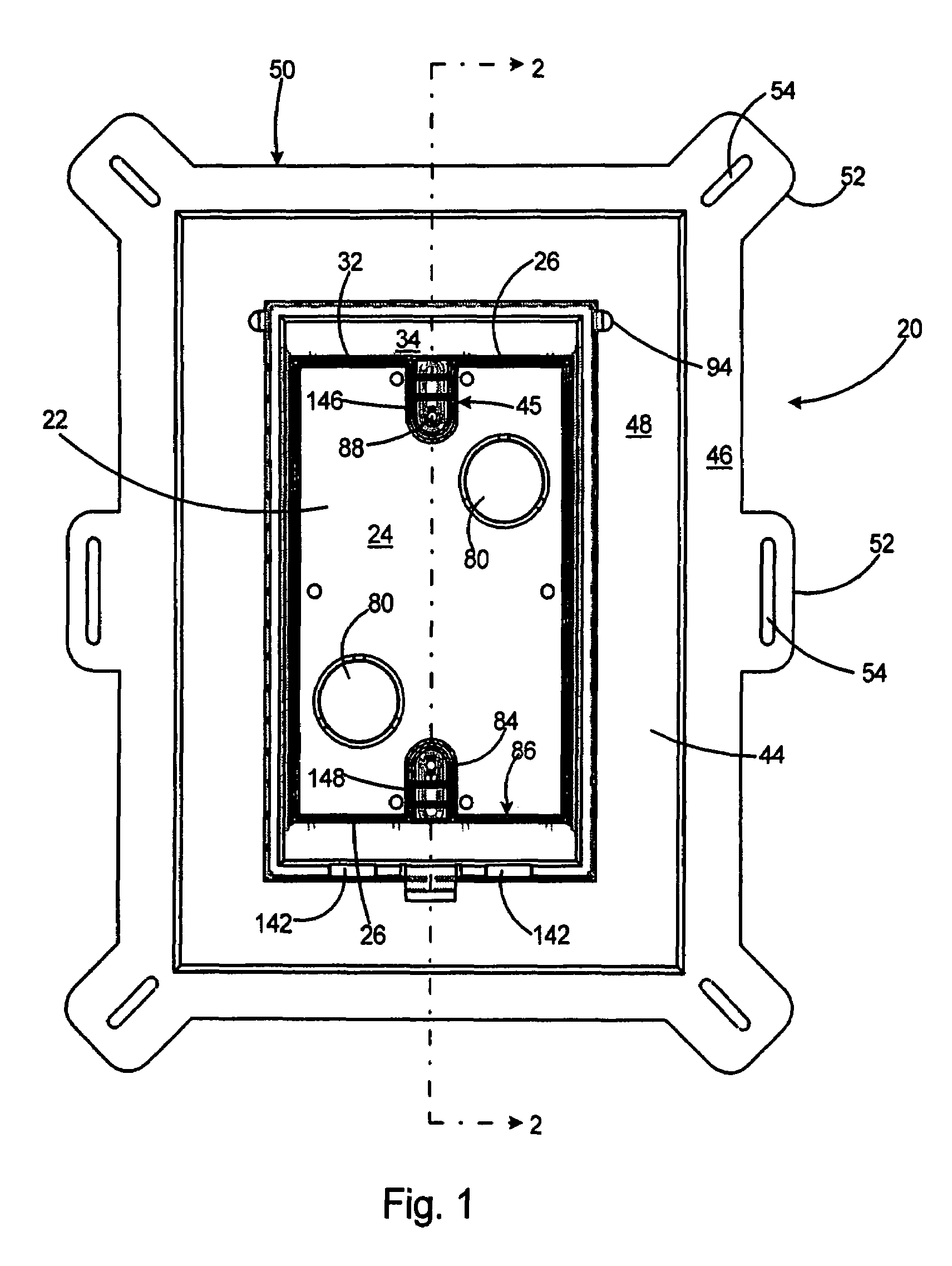
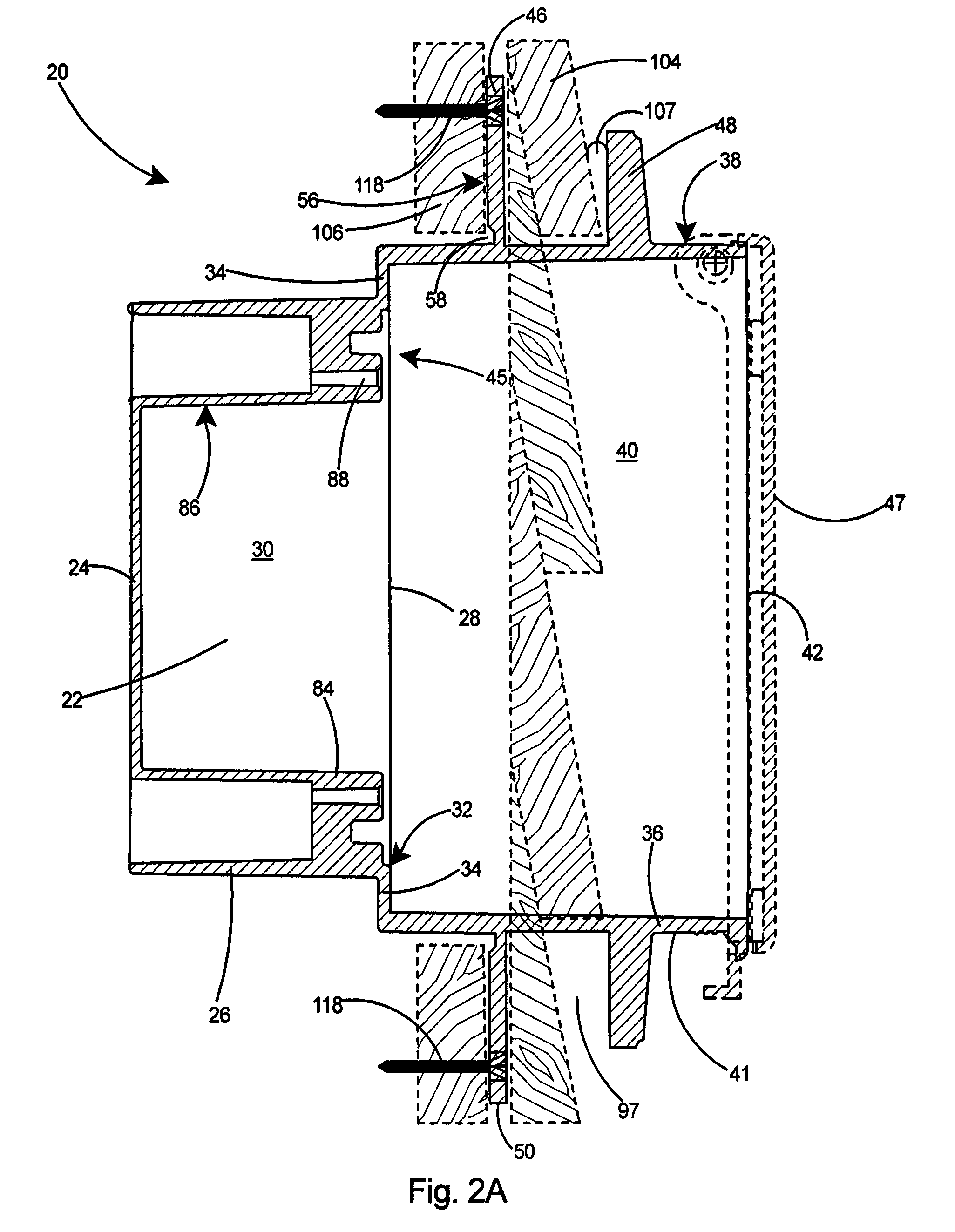
[0050]With reference to FIGS. 1-4, a recessed electrical box 20 according to the present invention is shown. The recessed electrical box includes a first box 22 having a back wall 24, peripheral sidewalls 26 extending orthogonally to the back wall 24, and a front opening 28 defining a cavity or first enclosure 30 therein. The peripheral sidewalls 26 of the first box 22 include a front edge 32 at the front opening 28. A transverse wall portion 34 extends outwardly and orthogonally from the peripheral sidewalls 26 at the front edge 32. Second peripheral sidewalls 36 extend orthogonally from the transverse wall portion 34 and form a second box 38 and a second enclosure 40 therein. The first box 22 and second box 38 may be molded in one piece from plastic and form a one-piece box member 41. Alternatively, the first box 22 and second box 38 may be formed of metal in one piece, or each box 22, 38 formed of metal and then secured together by conventional means. The second peripheral sidewa...

third embodiment

[0069]the recessed electrical box 110, shown at the bottom of FIG. 17, includes only a breakaway inner flange 46. If the building is under construction and the substrate 106 exposed, the inner flange 46 serves as a positioning arrangement for mounting the electrical box 110 at the proper depth. Fasteners 118 can then be driven through the inner flange 46 of the recessed electrical box 110 to secure it to the substrate 106.

[0070]Regardless of which embodiment of the recessed electrical box 20, 100, 110 is used, the electrical device will be positioned substantially behind the outside surface 138 of the building, thereby providing a great deal of protection to the electrical device. As shown in FIG. 4, the planar front edge 42 of the recessed electrical box 20 further includes one or more U-shaped slots 142 in the side walls 36 of the second box 38. As shown in FIG. 13, the cover member 47 also includes one or more U-shaped slots 144 in the stiffening side wall 95. When the cover memb...


PUM


Abstract

A recessed electrical box with a closeable cover member and at least one outward extending flange. The flange serves as a positioning arrangement to recess the electrical box at the correct depth with respect to the surface in which it will be mounted. The recessed electrical box includes of two pieces, including a one-piece electrical box and a one-piece cover member. An inner flange may be included for positioning the recessed electrical box with respect to the outer surface of the substrate on an unfinished building. The inner flange is removable to facilitate installation on a finished building, in which the finish layer such as siding or stucco is installed. The recessed electrical box may include a second, outer flange, for recessing the box at the correct depth with respect to a wall surface.

Description

[0001]This application is a Continuation of U.S. patent application Ser. No. 11 / 655,299 filed Jan. 19, 2007, now U.S. Pat. No. 7,294,781, which is a Continuation-In-Part of U.S. patent application Ser. No. 11 / 356,590 filed Feb. 16, 2006 and now U.S. Pat. No. 7,166,801, which is a Continuation-In-Part of U.S. patent application Ser. No. 11 / 264,857, filed Nov. 2, 2005 and now U.S. Pat. No. 7,045,713, which is a Continuation-In-Part of U.S. patent application Ser. No. 11 / 246,985, filed Oct. 7, 2005 and now U.S. Pat. No. 7,064,271, which is a Continuation-In-Part of U.S. patent application Ser. No. 11 / 185,256, filed Jul. 20, 2005 and now U.S. Pat. No. 7,115,820, which is a Continuation-In-Part of U.S. patent application Ser. No. 11 / 102,392, filed Apr. 8, 2005 and now U.S. Pat. No. 7,151,219, which is a Continuation-In-Part of U.S. patent application Ser. No. 11 / 070,344, filed Mar. 2, 2005 and now U.S. Pat. No. 6,965,078, which is a Continuation-In-Part of U.S. patent application Ser. No...

Claims


Application Information

Patent Timeline
Patent Type & Authority Patents(United States)
IPC IPC(8): H02G3/08
CPCH01R25/006H02G3/121H02G3/126H02G3/14H01R24/76H01R2103/00Y10S248/906
Inventor GRETZ, THOMAS J.
Owner ARLINGTON INDS
Why Eureka
Try Eureka