
Method for accelerated determination of occlusion between polygons

a polygonal occlusion and determination method technology, applied in the virtual environment, can solve the problems of difficult design of difficult code, and even more difficult to achieve robust and flexible visual effects

Active Publication Date: 2008-10-14
VALVE
View PDF24 Cites 2 Cited by
  • Summary
  • Abstract
  • Description
  • Claims
  • Application Information

AI Technical Summary

Benefits of technology

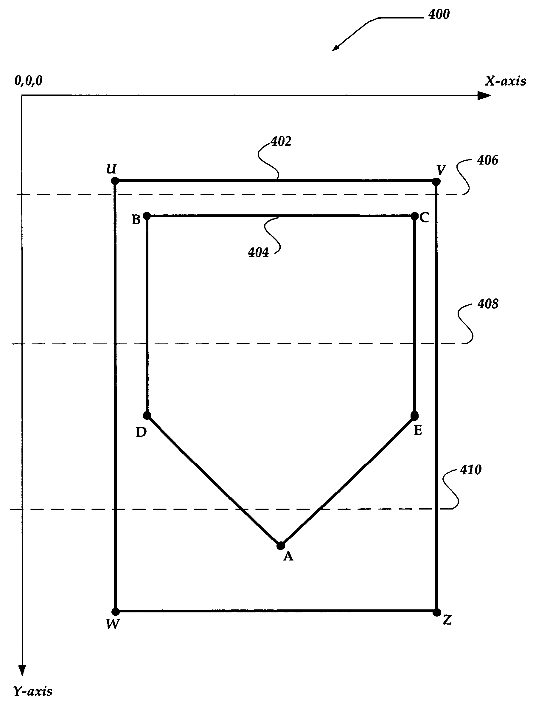
The present invention is about a system, method, and device for efficiently rendering computer games and other interactive environments. It focuses on the challenge of creating realistic visual effects that are also efficient for the hardware systems used to render them. The invention uses a boundary box to simplify the testing of occludee polygons and employs a variety of techniques to reduce the number of polygons needed to be drawn. Overall, the invention improves the efficiency and flexibility of creating visually rich interactive environments.

Problems solved by technology

However, creating robust and flexible visual effects that are also computationally efficient is a considerable challenge.
Such visual effects may be difficult to design, challenging to code, and even more difficult to render.
Drawing such a large number of polygons may be a task that is beyond the capacity of many of today's computer hardware systems.
However, even after using such techniques, there are often still too many polygons for today's hardware to render.
The problem is that scenes, such as in a game, often have very high depth complexity, that is, many layers of geometry underneath each pixel.
However, although in theory occlusion culling can remove a large number of invisible polygons, the computational cost of traditional occlusion culling approaches is often high.

Method used


Image

  • Method for accelerated determination of occlusion between polygons
  • Method for accelerated determination of occlusion between polygons
  • Method for accelerated determination of occlusion between polygons

Examples


Embodiment Construction

[0019]The present invention now will be described more fully hereinafter with reference to the accompanying drawings, which form a part hereof, and which show, by way of illustration, specific exemplary embodiments by which the invention may be practiced. This invention may, however, be embodied in many different forms and should not be construed as limited to the embodiments set forth herein; rather, these embodiments are provided so that this disclosure will be thorough and complete, and will fully convey the scope of the invention to those skilled in the art. Among other things, the present invention may be embodied as methods or devices. Accordingly, the present invention may take the form of an entirely hardware embodiment, an entirely software embodiment or an embodiment combining software and hardware aspects. The following detailed description is, therefore, not to be taken in a limiting sense.

[0020]Briefly stated, the present invention is directed to a system, apparatus, an...


PUM


Abstract

The invention describes a method and system for use in occlusion culling of polygons in an interactive environment, such as a game. The invention employs a boundary box to simplify the testing of occludee polygons. Occluders and occludees are also transformed into non-interpenetrating, non-overlapping polygons. Winged-edges are employed to minimize a per occludee computational cost due to precision problems that may arise at non-overlapping edges. The invention then proceeds through an active edge list to identify edge discontinuities (e.g., where an edge is added or removed from the active edge list). Depth analysis is employed to determine whether an occluder occludes an occludee at the edge discontinuity. Moreover, the invention only performs depth analysis for those locations of a screen display where an occludee is determined to reside, thereby minimizing unnecessary computations.

Description

FIELD OF THE INVENTION[0001]The present invention relates to a virtual environment, and in particular, but not exclusively, to efficient rendering of graphical polygonal models.BACKGROUND OF THE INVENTION[0002]As many devoted computer gamers may be aware, the overall interactive entertainment of a computer game may be greatly enhanced with the presence of realistic visual effects. However, creating robust and flexible visual effects that are also computationally efficient is a considerable challenge. Such visual effects may be difficult to design, challenging to code, and even more difficult to render.[0003]For example, a visual image that includes a large scene, such as a building interior, a city, mountain, and the like, may involve millions of polygons that need to be drawn. Drawing such a large number of polygons may be a task that is beyond the capacity of many of today's computer hardware systems. One solution to this problem recognizes that usually only a small part of such a...

Claims


Application Information

Patent Timeline
Patent Type & Authority Patents(United States)
IPC IPC(8): G06F17/00G06T1/00G06T15/00G06T15/40G09G5/00
CPCG06T15/40A63F13/355A63F13/52
Inventor JACOBSON, BRIAN
Owner VALVE
Learn More