
Spray arch controller for a carwash

Inactive Publication Date: 2008-10-21
WASHWORLD
View PDF24 Cites 56 Cited by
  • Summary
  • Abstract
  • Description
  • Claims
  • Application Information

AI Technical Summary

Benefits of technology

[0010]Another object of some embodiments is to alternately rotate a spray arch clockwise and counterclockwise to limit its cumulative rotation, wherein the arch can be rotated in one direction more than 180-degrees, or more than 270-degrees, or perhaps even 360-degrees, without over twisting an electrical cable that may lead to an electrical component mounted to the spray arch and without having to rely on rotating electrical contacts.
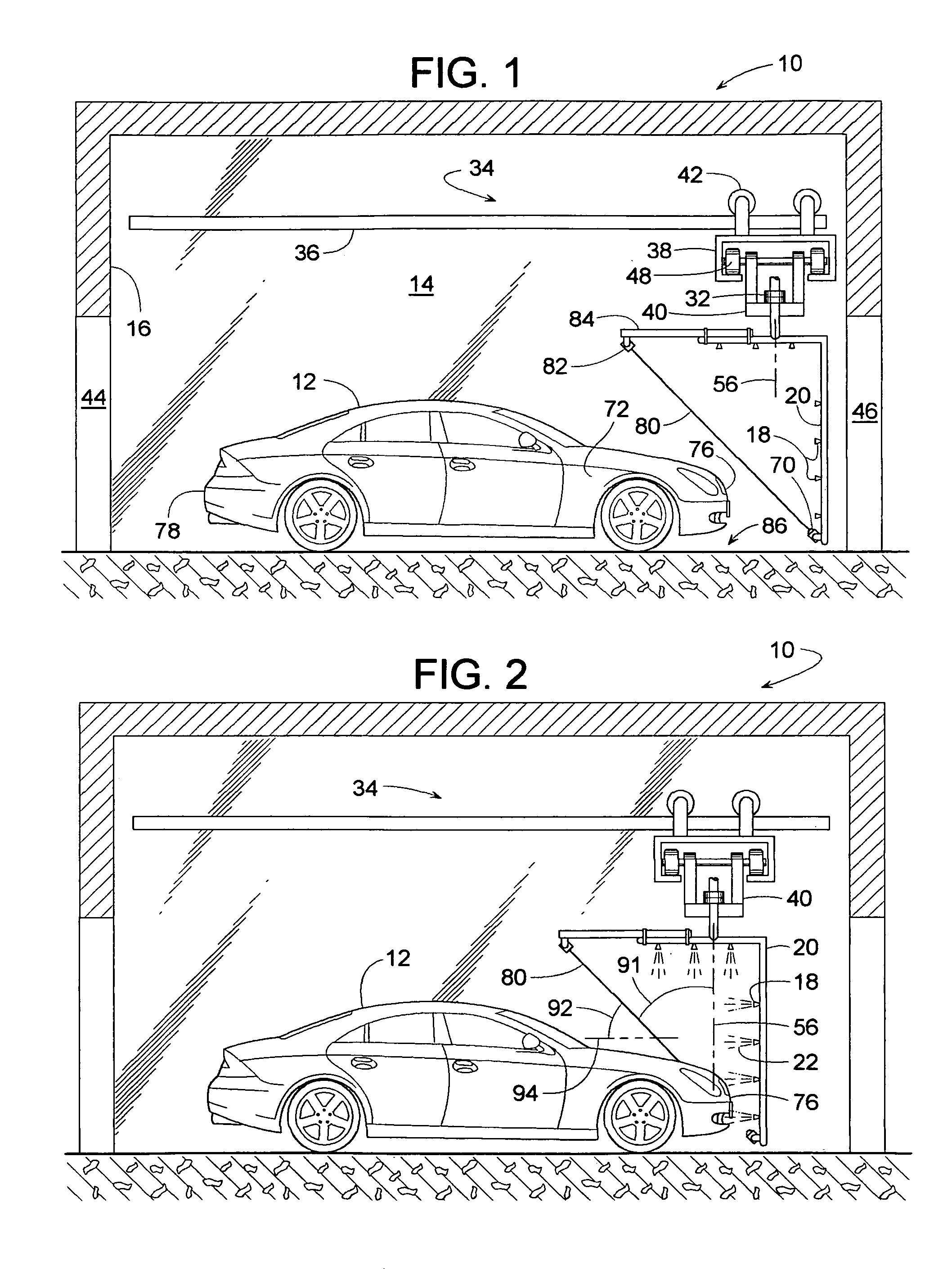
[0012]Another object of some embodiments is to have the beam projected at an angle of at least 20 to avoid shooting the beam through an open-sight opening in the vehicle and no more than 80 degrees so that the sensor and spray arch can stay a safe distance away from the vehicle.
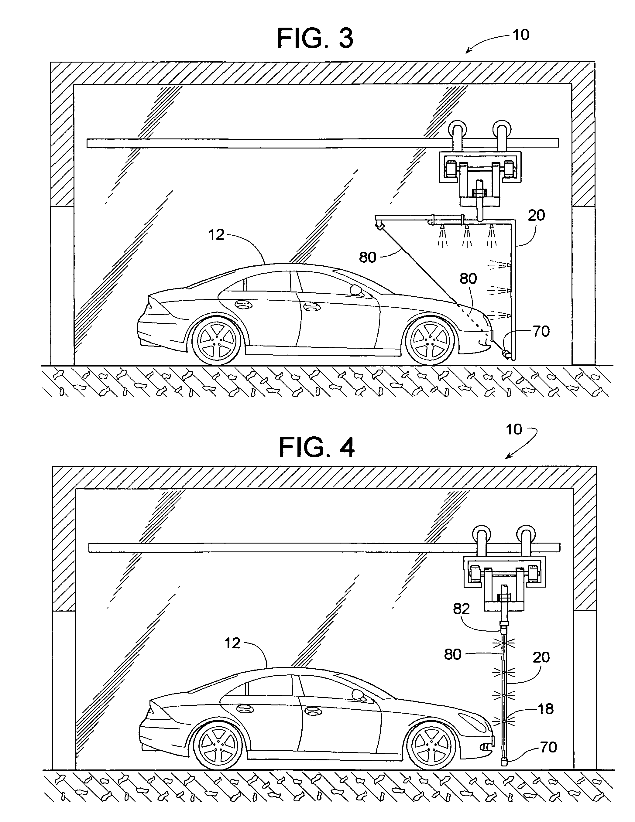
[0014]Another object of some embodiments is to mount just the sensor to the spray arch and an emitter at a stationary location, thereby reducing the number of electrical cables on the spray arch.
[0016]Another object of some embodiments is direct the path of a spray arch such that the vehicle obstructs a beam for substantially the entire distance that the arch travels along the length of the vehicle, whereby a momentary failure in the sensor or emitter would not be a problem.
[0017]Another object of some embodiments is direct the path of a spray arch such that the vehicle obstructs a beam for substantially the entire distance that the arch travels along the width of the vehicle, whereby a momentary failure in the sensor or emitter would not be a problem.

Problems solved by technology

The various sensors of a carwash can be problematic due to the harsh environment in which they operate.
Fog, water spray, dirt, strong chemicals, and ice are just a few of the common elements that can disrupt the operation of sensors.
Many sensors may provide false signals due to vehicles of widely varying design where the exterior surface of the vehicle may vary by color, shape, material (e.g., plastic, metal, glass), reflectivity, height, angle, etc.

Method used


Image

  • Spray arch controller for a carwash
  • Spray arch controller for a carwash
  • Spray arch controller for a carwash

Examples


Embodiment Construction

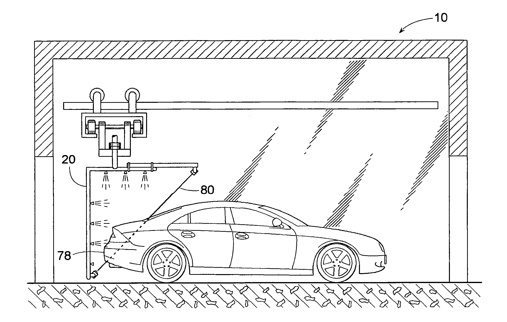
[0058]FIGS. 1-15 illustrate a carwash 10 and a method of washing a vehicle 12 in a wash bay 14. The term, “carwash” broadly represents any system for spray cleaning not just cars but any vehicle, wherein the term, “vehicle” represents any wheeled transporter. Examples of a vehicle include, but are not limited to, an automobile, truck, van, limousine, bus, mobile home, camper, etc. The term, “wash bay” represents any designated area or volume of space in which a vehicle can be cleaned. Although carwash 10 is shown having walls 16 that define wash bay 14, providing a carwash and wash bay without walls is well within the scope of the invention.

[0059]Three aspects of a conventional carwash include a spray arch, a parking display system, and a tire-engaging treadle switch. The parking display system typically provides visual signals that assist drivers in guiding their vehicle to a desired position within the wash bay. Parking display systems, for instance, may tell the driver when to dr...


PUM


Abstract

A carwash includes a single thru-beam or retroreflective photoelectric sensor that can determine the position of a vehicle's left side, right side, front end and back end. To accomplish this, the sensor is coupled to a spray arch that travels around the vehicle while spray washing the vehicle's exterior. In some embodiments, the sensor responds to a beam projected from an emitter that also travels with the spray arch, whereby the emitter, the sensor and the spray arch move in unison. The beam is preferably projected at an acute angle to a horizontal plane so that the sensor can detect the presence of the vehicle without the spray arch having to get too close. To avoid over twisting the sensor's electrical cable, the arch alternately rotates CW and CCW to limit cumulative rotation in any one direction. In some cases, the single sensor responds to beams from multiple emitters.

Description

BACKGROUND OF THE INVENTION[0001]1. Field of the Invention[0002]The subject invention generally pertains to a carwash and more specifically to a system for controlling the path of a spray arch.[0003]2. Description of Related Art[0004]To wash a vehicle in what is known as a touchless automatic carwash, the vehicle is usually parked at a desired location within a wash bay. Once a tire-engaging treadle switch or some other sensor system determines that the vehicle is properly parked, a controller commands an overhead supporting structure to move one or more spray arches (or some other type of pipe with a series of spray nozzles) around the vehicle to sequentially spray various mixtures of water, soap, and other chemicals at a temperature and pressure sufficient to flush dirt and grime off the vehicle.[0005]To maintain a desired spraying distance between the spray arch and the vehicle, the controller typically guides the movement of the arch in response to multiple additional sensors th...

Claims


Application Information

Patent Timeline
IPC IPC(8): B08B3/00
CPCB60S3/04
Inventor HUNTINGTON, ALAN G.JENSEN, PETER T.SMITH, KENNETH R.STARNES, BUDDY R.STOCK, DAVID C.HARTER, ROBERT J.
Owner WASHWORLD
Learn More