Workpiece holding jig

a technology for holding jigs and workpieces, which is applied in the field of workpiece holding jigs, can solve the problems of contaminating workpieces, reducing the quality and reliability of chip size packages (csp), and workpieces falling into, and achieves the effect of convenient carrying subsequently

Active Publication Date: 2008-10-21
DISCO CORP
View PDF5 Cites 10 Cited by
  • Summary
  • Abstract
  • Description
  • Claims
  • Application Information

AI Technical Summary

Benefits of technology

[0008]It is an object of the present invention to provide a workpiece holding jig capable of maintaining the form of a workpiece which does not fall into pieces when it is cut along predetermined dividing lines.
[0013]In the workpiece holding jig constituted according to the present invention, as areas sectioned by the first dividing lines and the second dividing lines of the workpiece are suction-held by the workpiece holding jig, when the workpiece is cut along the first dividing lines and the second dividing lines, it does not fall into pieces and can maintain its form, thereby making it easy to carry it subsequently.

Problems solved by technology

When the CSP substrate is cut with the cutting blade, however, a problem arises that burrs are formed on the connection terminals to cause a short circuit between adjacent connection terminals, thereby reducing the quality and reliability of a chip size package (CSP).
Further, when a workpiece such as a semiconductor wafer or the like besides the CSP substrate is cut with the cutting blade, a problem also occurs that fine chips are adhered to the surface of the workpiece, thereby contaminating the workpiece.
The above water jet cutting processing involves a problem that even though a protective sheet is affixed to the back surface of the workpiece such as a CSP substrate, processing water penetrates the protective sheet to cut the workpiece and consequently, the workpiece falls into pieces, thereby making it difficult to carry the workpiece successively.
A similar problem occurs even in laser beam processing for cutting the workpiece by applying a laser beam thereto.

Method used


Image

  • Workpiece holding jig
  • Workpiece holding jig
  • Workpiece holding jig

Examples


Embodiment Construction

[0035]Preferred embodiments of a workpiece holding jig constituted according to the present invention will be further described in detail hereinunder with reference to the accompanying drawings.

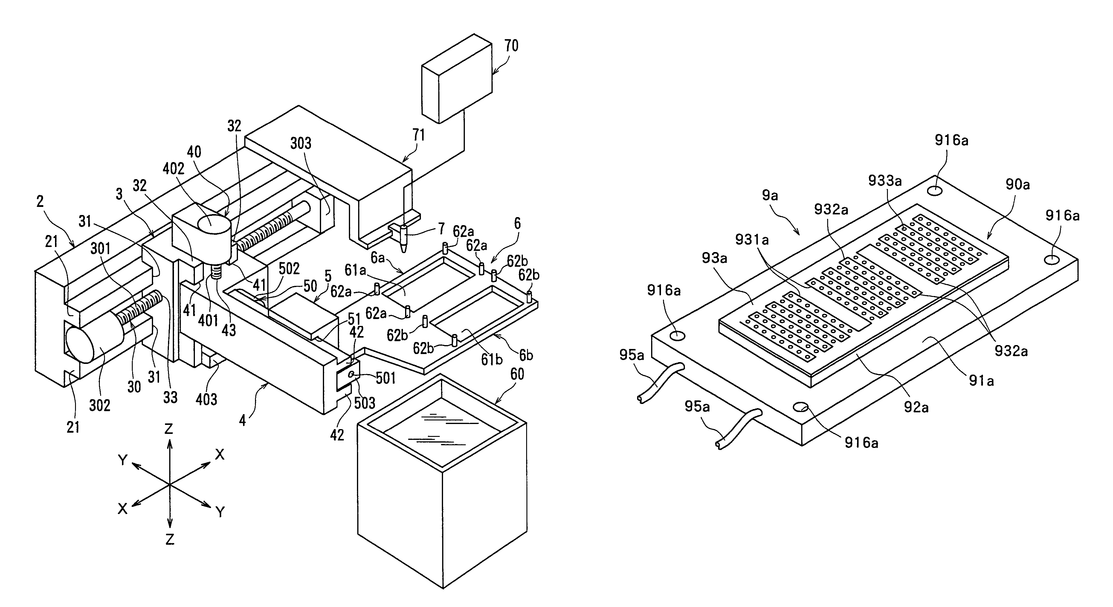
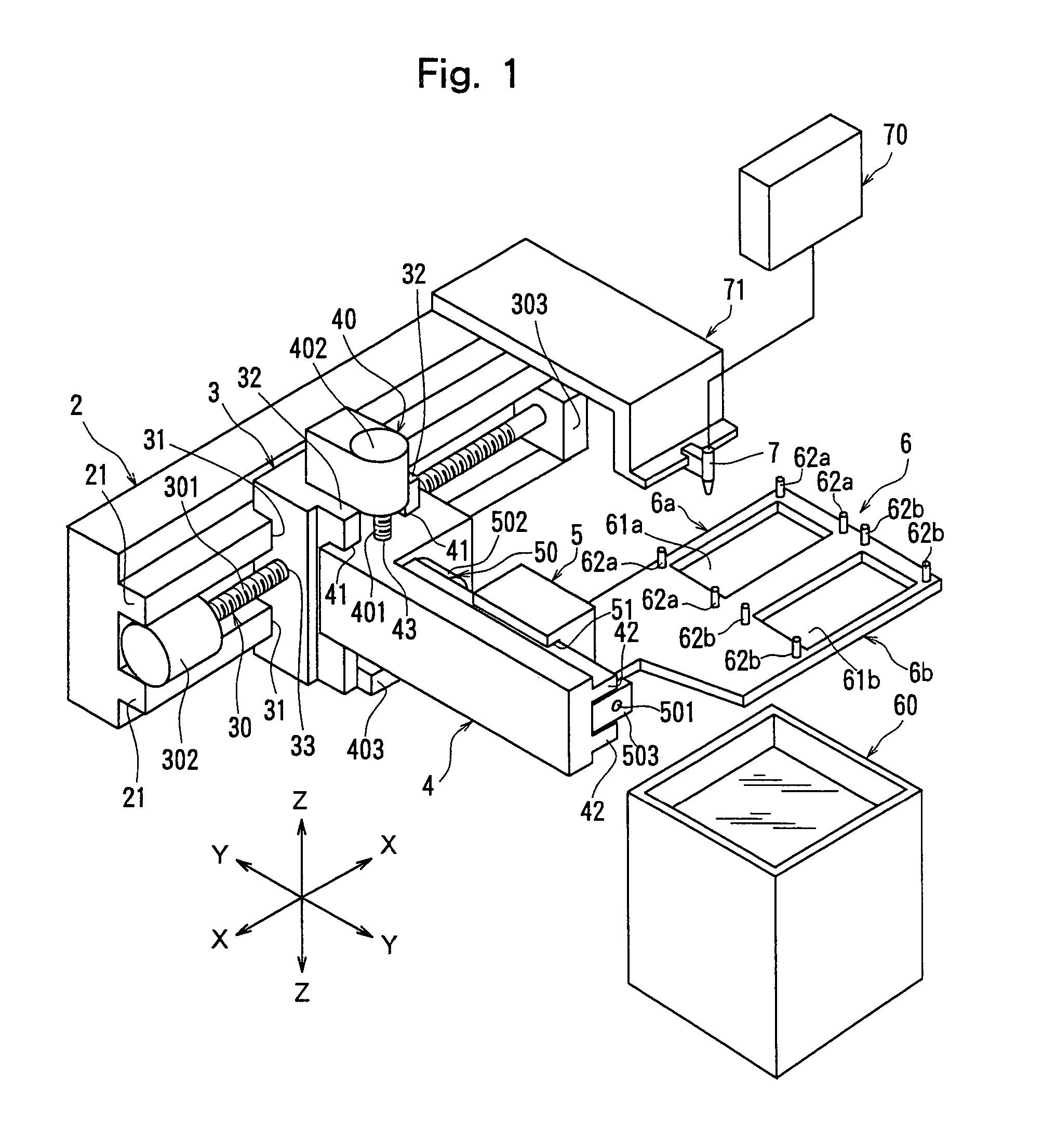
[0036]FIG. 1 is a perspective view of principal sections of a water jet-processing machine equipped with a workpiece holding jig constituted according to the present invention. The water jet-processing machine shown in FIG. 1 comprises a stationary base 2, a first movable base 3, a second movable base 4 and a third movable base 5. A pair of guide rails 21 and 21 extending parallel to each other in the direction indicated by an arrow X are formed on the flank on this side of the stationary base 2.

[0037]The first movable base 3 has a pair of to-be-guided grooves 31 and 31 that are formed in one flank opposed to the above stationary base 2 in the direction indicated by the arrow X and are slidably fitted to the pair of guide rails 21 and 21 provided on the stationary base 2, and a pair of guide ...


PUM

PropertyMeasurementUnit
diameteraaaaaaaaaa
distanceaaaaaaaaaa
suctionaaaaaaaaaa

Abstract

A workpiece holding jig for holding a workpiece having a plurality of first dividing lines extending in a predetermined direction and a plurality of second dividing lines formed in a direction intersecting the plurality of first dividing lines on the workpiece holding table of a processing machine for cutting the workpiece along the plurality of first dividing lines and the plurality of second dividing lines, wherein the workpiece holding jig has a plurality of through-grooves corresponding to the plurality of first dividing lines and the plurality of second dividing lines formed on the workpiece, a plurality of suction-holes which are open at the top and formed at positions corresponding to a plurality of areas sectioned by the plurality of first dividing lines and the plurality of second dividing lines of the workpiece and suction-passages that are formed at positions where they do not intersect the plurality of through-grooves and connected to the plurality of suction-holes.

Description

FIELD OF THE INVENTION[0001]The present invention relates to a workpiece holding jig for holding a workpiece on the workpiece holding table of a processing machine such as a water jet-processing machine for cutting a workpiece such as a semiconductor wafer or the like by squirting a jet of high-pressure water thereto.DESCRIPTION OF THE RELATED ART[0002]In the production process of a semiconductor device, individual semiconductor chips are manufactured by forming a circuit such as IC or LSI in a large number of areas arranged in a lattice pattern on the front surface of a substantially disk-like semiconductor wafer and then, dicing the semiconductor wafer into the areas having each a circuit formed thereon along predetermined cutting lines called “streets”. The thus divided semiconductor chips are packaged, and widely used in electric appliances such as cellular phones, personal computers or the like.[0003]Lighter and smaller electric appliances such as cellular phones, personal comp...

Claims


Application Information

Patent Timeline
Patent Type & Authority Patents(United States)
IPC IPC(8): B25B11/00B24C5/02B28D1/04B28D5/00H01L21/00H01L21/304
CPCB25B11/005B28D5/0094H01L21/67092Y10S269/903Y10S269/90
Inventor UMAHASHI, TAKAYUKIKIMURA, KEN
Owner DISCO CORP
Why Eureka
Try Eureka