
Safety binding

a safety and binding technology, applied in the direction of ski bindings, sports equipment, skiing, etc., can solve the problems of skier falling, skier being unsuitable for skiing safety, and increasing the risks of skier taking

Inactive Publication Date: 2008-10-21
SALOMON SA
View PDF21 Cites 8 Cited by
  • Summary
  • Abstract
  • Description
  • Claims
  • Application Information

AI Technical Summary

Benefits of technology

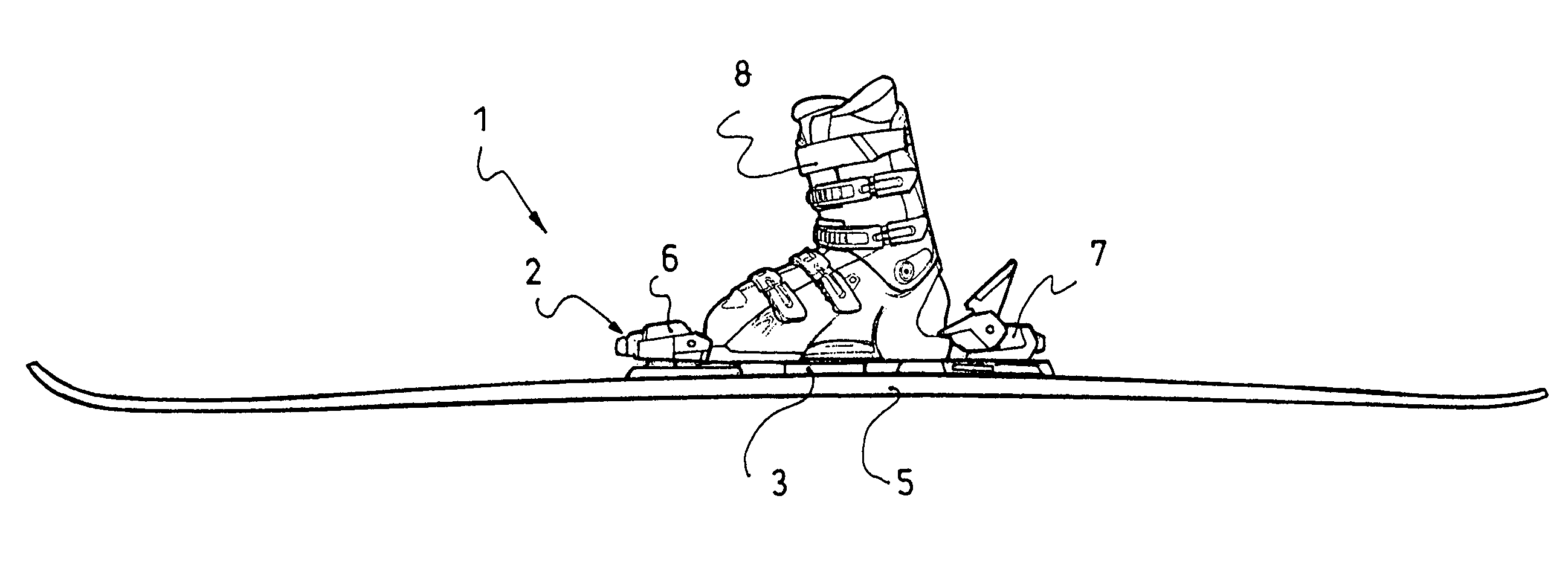
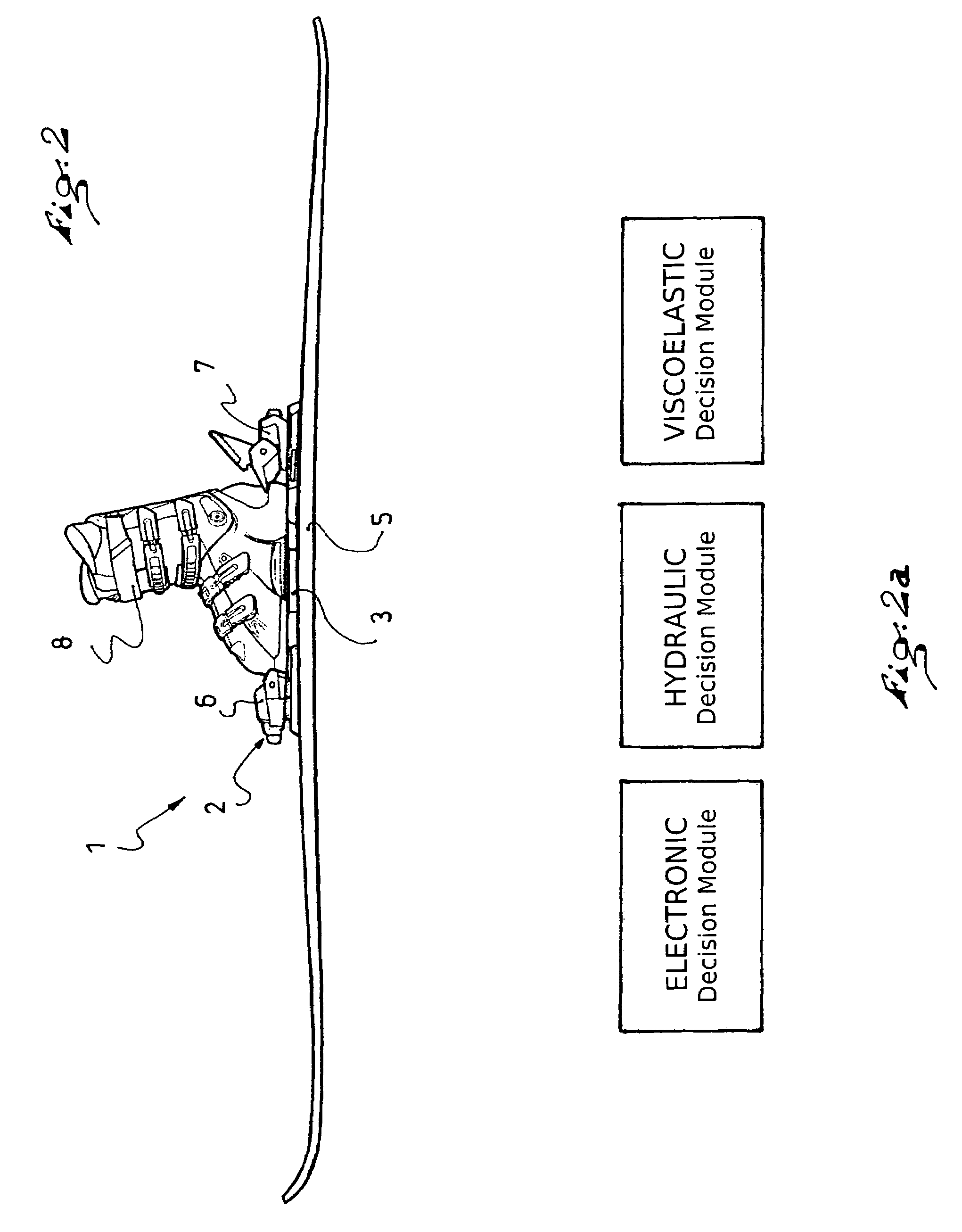
The invention proposes a safety binding device for binding a boot onto a gliding board, which makes it possible to overcome the limitations of the known prior art devices. The device includes releasable retaining mechanisms of the mechanical, hydraulic, or viscoelastic type which actuate a release as a function of the forces to which the boot is subjected, and an electronic circuit controlling the release action of the releasable retaining mechanisms. The release action occurs as soon as the magnitude of the force is greater than a given threshold, which is determined based on the skier's parameters in conformance with theISO standards. The device can be pre-adjusted for each skier to ensure optimal safety during skiing activities.

Problems solved by technology

The lack of dependency of the release of the boot on the duration of the application of forces can increase the risks taken by the skier.
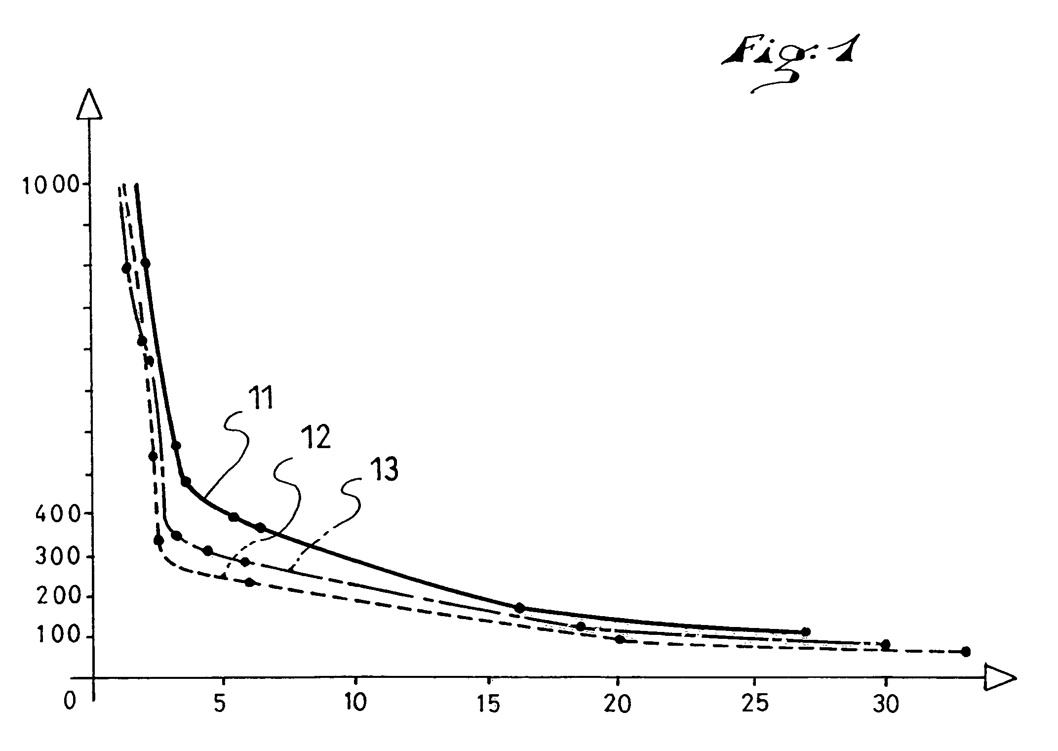
However, if the binding device release principle does not take into account the duration of the application of forces, or does so inadequately, the binding will release and therefore cause the skier to fall as soon as a substantial force is applied, even for a very short period of time.
This type of release, undesirable for the skier's safety, even potentially dangerous, is referred to as an ill-timed release.
Under these circumstances, the skier assumes the risks involved when he / she skis at lower speeds.
In addition, it is known that the human body can sustain serious injuries, even when subjected to low forces, provided that these forces are applied to the body for relatively long periods of time.
In such a situation, the skier may be injured if he / she cannot manually actuate the release.

Method used


Image

  • Safety binding
  • Safety binding
  • Safety binding

Examples


Embodiment Construction

[0021]The International Organization for Standardization (ISO) has drawn up an international standard for the assembly, adjustment, and inspection of a ski / binding / boot system (ISO 11088). This standard specifies procedures particularly intended for retailers of sporting goods for assembling and adjusting ski binding mechanisms.

[0022]The ISO 11088 standard defines optimal, theoretical release moments as a function of the skier's weight, height, and type. For a skier weighing between 67 and 78 kg (i.e., a range of approximately 147-172 lbs), for example, it is recommended that the binding disengage and release the boot when the value of the moment of the forces to which the boot is subjected is such that the component along the z-axis (vertical axis) reaches 50 N.m. (i.e., approximately 36.8 ft.-lbs.).

[0023]Binding manufacturers conform to standards and, in order to facilitate the adjustment operation carried out by technicians, they mark their products with scales graduated between ...


PUM


Abstract

A safety binding device for binding a boot on an alpine ski including a releasable retaining mechanism of the mechanical, hydraulic, viscoelastic type, which actuate a release as a function of the forces to which the boot is subjected and as a function of the duration Δt of the application of such forces. The release action occurs as soon as the magnitude of the force is greater than an actual release threshold, Sr, which is dependent upon the duration Δt of the application of force, such that if duration is greater than one second, the actual release threshold is between 50% and 75% of the theoretical release threshold, St, whereby: Δt>1 s; 0.75×St≧Sr(Δt)≧0.5×St, with the theoretical release threshold St being determined as a function of the skier's parameters in conformance with ISO standards. In a particular embodiment, the release principle, which defines the actual release threshold as a function of the duration, Sr (Δt), is of the exponential decrease type: Sr(Δt)=a+exp[(b−Δt) / c]; whereby a, b, and c are parameters.

Description

CROSS-REFERENCE TO RELATED APPLICATION[0001]This application claims priority under 35 U.S.C. §119 of French Patent Application No. 05.10723, filed on Oct. 20, 2005, the disclosure of which is hereby incorporated by reference thereto in its entirety.BACKGROUND OF THE INVENTION[0002]1. Field of the Invention[0003]The invention relates to a safety binding device for binding a boot to a gliding board, the binding device including releasable retaining elements.[0004]2. Description of Background and Relevant Information[0005]Safety bindings having a toe piece and a heel piece to hold a ski boot therebetween are known from the prior art. Such safety bindings disengage and release the ski boot when the toe piece and the heel piece are subjected to forces that exceed a certain threshold. The release threshold can be changed by adjusting the pre-tensioning of the springs positioned in the toe piece and the heel piece. In an essentially mechanical binding, such as that described herein, the ac...

Claims


Application Information

Patent Timeline
Patent Type & Authority Patents(United States)
IPC IPC(8): A63C9/00A63C9/08A63C9/088
CPCA63C9/088
Inventor DAMIANI, LAURENTDESARMAUX, PIERREBRUNET, CHRISTIANARNOUX, PIERRE JEAN
Owner SALOMON SA
Learn More