Cross axis ball and socket joint with sealing ring for cross axis sleeve ends

a cross-axis ball and socket joint technology, applied in the direction of couplings, rod connections, mechanical devices, etc., can solve the problems of reducing the crush load for a certain diameter, and difficult sealing of cross-axis joints, etc., to achieve simple design, reduce the crush load, and reduce the crush load. a certain diameter

Inactive Publication Date: 2008-10-21
ZF FRIEDRICHSHAFEN AG
View PDF7 Cites 22 Cited by
  • Summary
  • Abstract
  • Description
  • Claims
  • Application Information

AI Technical Summary

Benefits of technology

[0007]It is an object of the invention to provide an improved ball and socket joint, particularly a cross axis joint that is free of the problems noted above and which is simple in design, rugged in construction and is economical to manufacture.
[0013]The invention provides improved sealing performance including an increase sealing area / protection as well as a possible use of “thick coatings (Everlube, Geomet). The sealing area is over one surface, not multiple surfaces. The ball sleeve can be straight or any easily produced shape so as to remove some of the complexity from the formation of the ball sleeve in order to compensate for the additional costs of the ring. The invention allows for the potential use of a ball sleeve raw part with minimum machining versus typical screw machine sleeve.
[0016]The invention also presents the advantage that there is a potential for reduced coating costs of coating the entire stud (pivot pin) versus only covering the sealing rings or the cap part (caps are symmetrical so only one piece is coming into a production area). Further, it is possible to roughen an inner axially extending surface (and also the radially extending surface) of the sealing ring surface, thereby increasing the friction of the clamped connection (whereby it is possible to downsize the bolt and the joint). Such a cross axis or X-axis joint according to the invention is more robust than prior joints and can pass key-life testing based on the ring providing an amount of sealing surface for opportunity to add pre-seal lips.

Problems solved by technology

Washers and built up inner sleeves are known to be provided between the connection part and the sleeve end face, but they show the disadvantage that either the washers are pressed in, into the inner diameter and reduce therefore the crush load, or increase the outer diameter or the built up ones also reduce the crush load for a certain diameter.
Currently it is difficult to seal cross-axis joints, this is primarily due to lack of sealing areas and “protection” of the mating part surface.
There may be a quality concern that the washers could fall off during delivery to the customer.
The shaping or framing of the pivot ends lowers the material properties and lowers the ability to withstand clamping forces.
These then limit the bolt size that can fit through the sleeve opening or the construction must be oversized.

Method used


Image

  • Cross axis ball and socket joint with sealing ring for cross axis sleeve ends
  • Cross axis ball and socket joint with sealing ring for cross axis sleeve ends
  • Cross axis ball and socket joint with sealing ring for cross axis sleeve ends

Examples


first embodiment

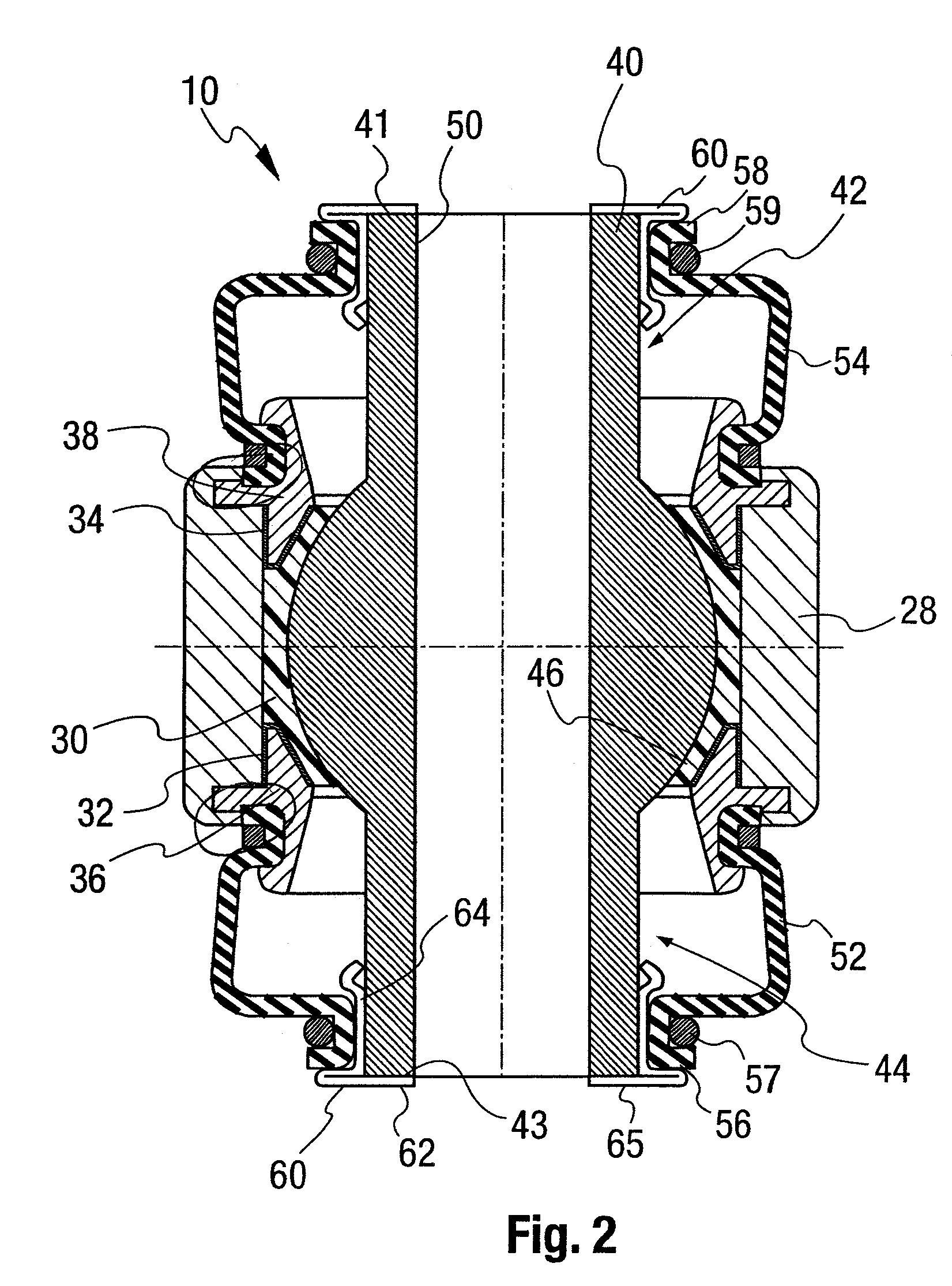
[0027]FIG. 2 shows the ball joint 10 according to the invention. A metallic housing 30 is provided supporting a bearing shell 30 in an inner space. The bearing shell 30 is held in place by a lower intermediate part 32 and lower housing ring 36 at one end and by an upper intermediate part 34 and upper housing ring 38. The rings 36 and 38 are held in position by a deformation of the ends of the material of the main housing part 28, to lock the rings 36 and 38 in position. Within the bearing shell 30 a ball sleeve 40 is provided, particularly with a ball sleeve bearing surface 46 in contact with the bearing shell 30. The ball sleeve 40 has the inner through opening 50 and has first and second (shown as upper and lower) pivot pins (also referred to as studs) with outer sleeve surfaces 42 and 44. The ball sleeve 40 also has a first end face 41 and a second end face 43. A sealing ring 60 is provided at each end of the ball sleeve 40. Each sealing ring 60 includes a radially extending part...

third embodiment

[0030]A third embodiment according to invention is provided with the structure as shown in FIG. 3 or 4 (or one of the other embodiments) but with a roughened inner surface at extending part 62 and / or the axially extending part 64. Additionally, or as an alternative, the facing surfaces (side 42, 44 and / or bottom 43, 41) of ball sleeve 40 may be roughened. FIG. 5 shows a sealing ring 60″ with an axially extending part 64 with an inner surface 66 in contact with the outer surface 44. The radially extending part 62 and the axially extending part 64 do not need to have a bent part 73, 71 but this may also be provided otherwise as shown in FIGS. 3 and 4. The contact and the connection of axially extending part 64 to outer surface 44 is in the form of an interference fit. Further, good connection properties may be obtained in this regard wherein the surface 66 (or the outer surface of 44 or 42) are roughened to increase friction. This interference fit and / or roughened surface fit provides...

fourth embodiment

[0031]FIG. 6 shows a cross-sectional view of a fourth embodied according to the invention. a sealing ring 90 is provided in place of the sealing ring 60 shown in FIG. 2. The sealing ring 90 provides a sealing seat 98 for receiving the end 56 (or 58) of the bellows seal 52 (or 54). However the sealing ring 90 is provided as a thick piece of metal with machined surfaces with a surface 92 at the end face 43 (or 41) and a contact surface 91 that will be in contact with the connection part (20 or 22). The machined or otherwise provided surfaces also include a radially protruding part 93 with one side protruding into a groove 72 at the outer sleeve surface 44 (or 42) and another side protruding to form the seat 98. The sealing ring 90 may be pressed onto the end of the sleeve 40 allowing the radially protruding part 93 to engage the grooved 72 to lock the sealing ring 90 in place.


PUM


Abstract

A ball joint, is provided in the form of a cross axis joint with a housing, a bearing shell in the housing and a ball sleeve. The ball sleeve includes a ball portion with a bearing surface cooperating with the bearing shell and a first pivot pin and a second pivot pin extending from said ball portion in an axial direction. The ball sleeve has an inner surface defining a through hole (50) for receipt of a connection bolt. The first pivot pin has a first end with a first outer surface (42) and a first annular end face (41) and the second pivot pin has a second end with a second outer surface (44) and a second annular end face (43). Sealing rings (60, 60′, 60″, 90, 95) are provided, each having a first axially extending portion extending along the first outer surface and having a sealing area outer surface defining a bellows seal seat (64, 98) and a radially extending portion extending along the end face. Each bellows seal (52, 54) is connected to the housing at one end and connected to said bellows seal seat (64, 98) at another end.

Description

FIELD OF THE INVENTION[0001]The present invention relates to cross axis joints in general and more particularly to cross axis ball and socket joint constructions having a ball sleeve with a through hole and a central ball with pivot pin ends (sleeve ends) having a sealing area on the outer surface for connection with a bellows element (sealing boot).BACKGROUND OF THE INVENTION[0002]Cross axis joints are known that include a central ball joining two pivot pins (stud ends). Such ball-and-socket joints make possible a controlled movement of two adjacent components in relation to one another. The central ball joint is mounted in a bearing shell which is supported within a housing. The ball and pivot pin structure is hollow providing a ball sleeve for receiving a bolt.[0003]A cross axis joint is a ball-joint especially designed to carry loads in a radial direction and transfer such loads to a mating part by clamping force and friction. Typically, a two-sided device (connection part frame...

Claims


Application Information

Patent Timeline
Patent Type & Authority Patents(United States)
IPC IPC(8): F16C11/00
CPCF16C11/0614F16C11/0671F16J3/042Y10T403/32729Y10T403/32631Y10T403/31Y10T403/315F16C11/06F16C11/00
Inventor HOLMES, ERICFEHRE, FRANKFISCHER, MARKUS
Owner ZF FRIEDRICHSHAFEN AG
Why Eureka
Try Eureka