Clamping fixture for detachably fastening a disk-shaped tool

a technology of detachable fastening and fixing fixture, which is applied in the direction of manufacturing tools, woodworking apparatus, grinding machine components, etc., can solve the problems of automatic displacement of the supporting flange away from the tool, accidental loosening of the locknut, and increase the clamping for

Inactive Publication Date: 2008-10-21
ROBERT BOSCH GMBH
View PDF10 Cites 19 Cited by
  • Summary
  • Abstract
  • Description
  • Claims
  • Application Information

AI Technical Summary

Benefits of technology

[0008]The present invention is based on the idea of providing a locking mechanism with which the supporting flange can be locked in its clamping position which is displaced axially in the direction toward the tool. The supporting flange must be manually released and the driving action of the working spindle must be halted before the supporting flange can be rotated relative to the working spindle again and, therefore, displaced axially away from the tool, which allows the fastening element to be loosened easily and without the use of any aids. A locknut, in particular, which can be screwed onto an outer thread of the working spindle and rotated opposite to the disk-shaped tool is a potential fastening element.
[0009]It is also feasible, however, to provide an outer flange as the fastening means, which is held on the working spindle by the clamping screw. The inventive design of the clamping device prevents the fastening element from being loosened accidentally, since the operator must always intervene intentionally to enable axial displacement of the supporting flange in the direction toward the driven gear. A further advantage of the inventive clamping device is that the tool need not be modified—any common commercial tool can be installed. When the clamping device is located inside the gearbox housing, it is protected from dirt and moisture.
[0011]To loosen the supporting flange without the use of aids, it must first be released. To do this, the supporting flange must first be locked when it reaches a specified axial position, preferably a position with the maximum axial deflection. To increase the operating comfort of the clamping device, the present invention provides that the locking mechanism of the supporting flange can be actuated automatically. This can prevent the clamping device from being operated improperly.
[0013]To ensure optimal locking, it is advantageous to provide several spring-loaded locating bolts which are located in the circumferential direction and are separated from each other. They are preferably positioned symmetrically and can be actuated using a central push button.

Problems solved by technology

When the working spindle is rotated, the supporting flange moves axially in the direction of the tool, which increases the clamping force.
The disadvantage of the known clamping device, however, is that the supporting flange is automatically displaced away from the tool when the working spindle stops, without intervention by the operator.
The locknut is therefore always easy to loosen when the drive is switched off, which can result in the locknut being loosened accidentally even though the operator intends to continue using the portable power tool.

Method used


Image

  • Clamping fixture for detachably fastening a disk-shaped tool
  • Clamping fixture for detachably fastening a disk-shaped tool
  • Clamping fixture for detachably fastening a disk-shaped tool

Examples


Embodiment Construction

[0024]Identical components and components with identical functionality are labeled with the same reference numerals in the Figures.

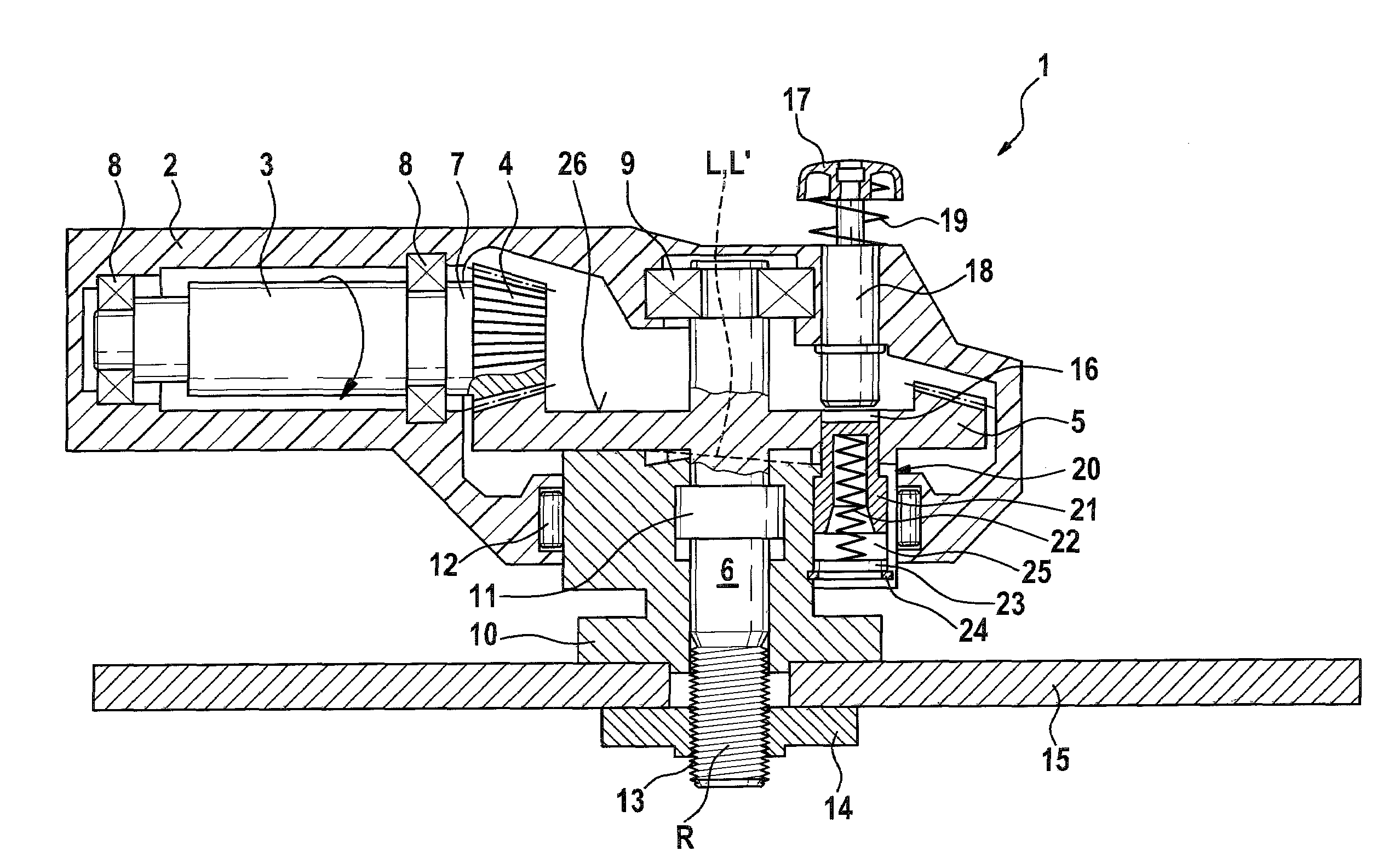
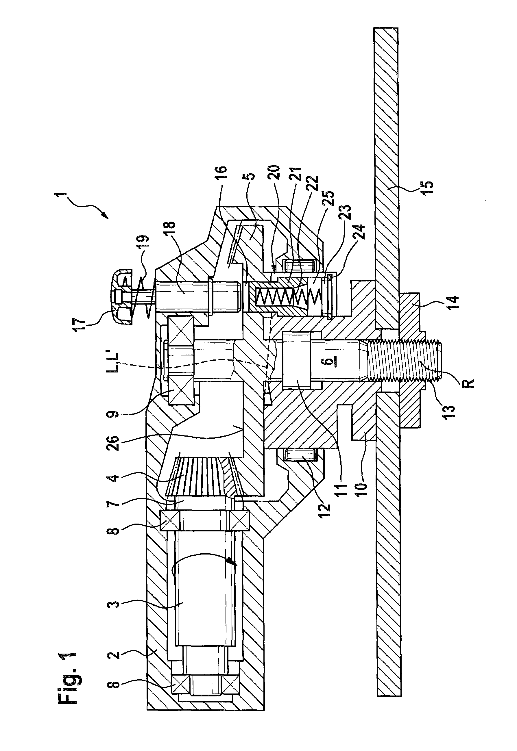
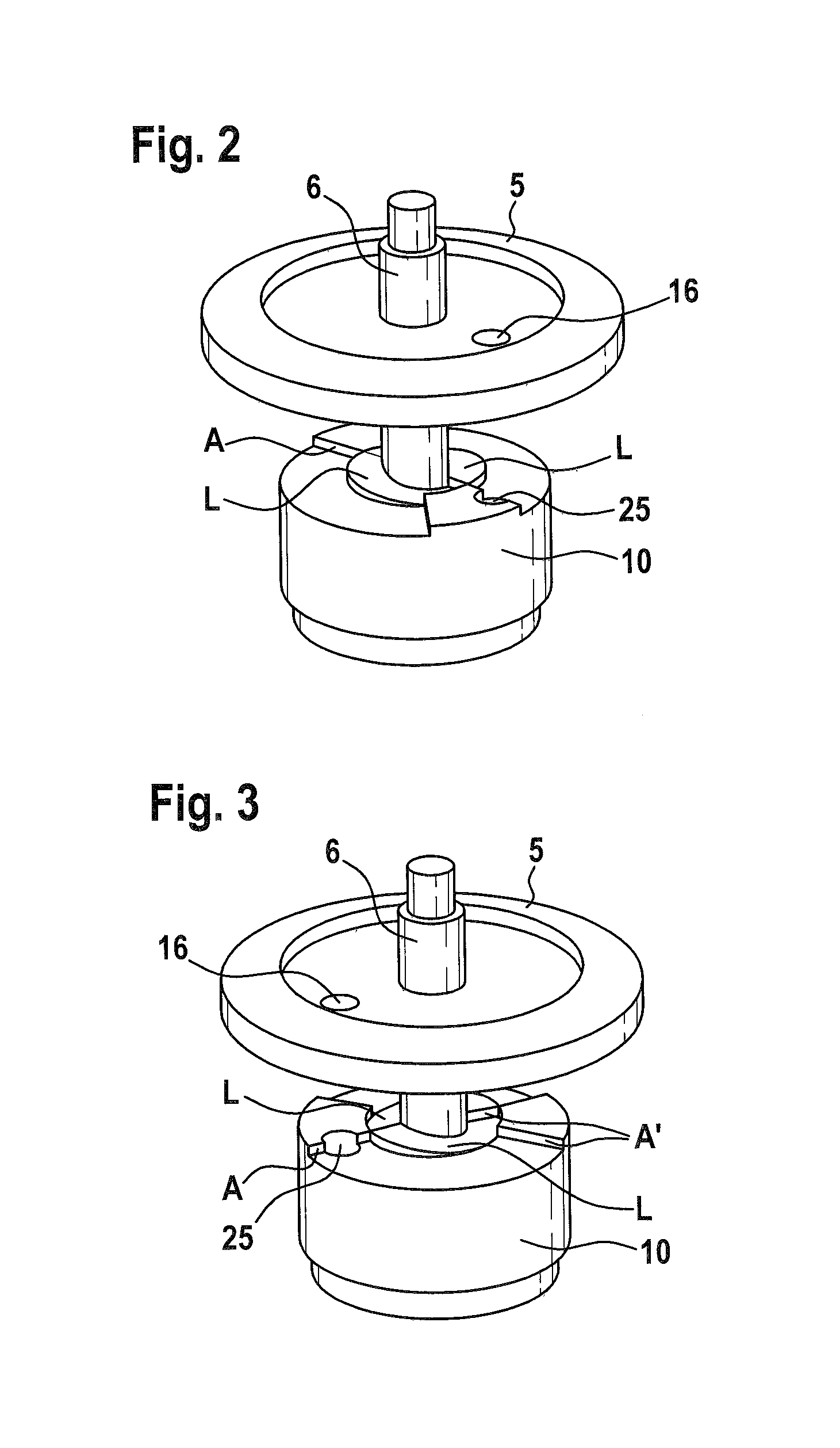
[0025]Shown in FIG. 1 is a portable power tool 1 with a housing 2, an electric motor-driven drive 3, a drive pinion 4 driven by drive 3, a driven gear 5 which meshes with drive pinion 4 and is designed as a crown wheel, and a working spindle 6 which is non-rotatably coupled with driven gear 5.

[0026]Drive pinion 4 is mounted on a motor shaft 7 which is rotatably supported via two separated bearings 8. Working spindle 6 is supported by a spindle bearing 9 such that it is rotatable and axially non-displaceable relative to housing 2. Working spindle 6 is rotatably supported via a further spindle bearing 11 such that it is rotatable relative to a supporting flange 10. A supporting flange bearing 12 is provided to rotatably support supporting flange 10 relative to housing 2. This allows supporting flange 10 to be displaced axially.

[0027]A disk-shaped tool 15—a...


PUM


Abstract

A clamping fixture for detachably fastening a disk-shaped tool on a rotatably driven working spindle with a driven gear includes a fastening element a supporting flange arranged so that the tool is accommodated between the fastening element and the supporting flange and rotatably displaceable relative to the working spindle in the tightening direction and axially in a direction toward the tool. The supporting flange is displaceable relative to the working spindle in a release direction and axially away from the tool when the fastening element is released, and is lockable with the working spindle or a component which is non-rotatably connected with the working spindle in a position which is displaced axially in a direction of the tool, and the supporting flange cannot be displaced axially away from the tool until a lock is released.

Description

CROSS-REFERENCE TO A RELATED APPLICATION[0001]The invention described and claimed hereinbelow is also described in German Patent Application DE 10 2006 001 986.5, filed Jan. 16, 2006. This German Patent Application, whose subject matter is incorporated here by reference, provides the basis for a claim of priority of invention under 35 U.S.C. 119(a)-(d).BACKGROUND OF THE INVENTION[0002]The present invention relates to a clamping fixture for detachably fastening a disk-shaped tool on a rotatably driven working spindle. Clamping fixtures of this type are suited for use in portable power tools in particular, such as angle grinders, portable circular saws, etc.[0003]Publication DE 196 49 514 A1 makes known a clamping fixture with which a disk-shaped tool is accommodated between a locknut and a supporting flange. When the working spindle is rotated, the supporting flange moves axially in the direction of the tool, which increases the clamping force. The supporting flange is spring-loaded ...

Claims


Application Information

Patent Timeline
Patent Type & Authority Patents(United States)
IPC IPC(8): B24B23/00
CPCB24B45/006B27B5/32
Inventor HABELE, MICHAEL
Owner ROBERT BOSCH GMBH
Why Eureka
Try Eureka