
Communication relay device with redundancy function for line in network in accordance with WAN environment and communication system using the same

a communication relay and network technology, applied in the field of communication relay devices with redundancy functions for lines in networks in accordance with wan environment, can solve problems such as dangerous data frame transmission, inability to perform frame transmission from blocked ports at all, and inability to achieve data frame transmission. the effect of redundant data outflow and improved line efficiency in the network

Inactive Publication Date: 2008-10-21
ANRITSU CORP
View PDF10 Cites 8 Cited by
  • Summary
  • Abstract
  • Description
  • Claims
  • Application Information

AI Technical Summary

Benefits of technology

[0093]The present invention has been made in order to solve the foregoing problems. It is an object of the present invention to provide a communication relay device with a redundancy function for a line in a network in accordance with a WAN environment capable of reducing outflow of redundant data to the line, thereby improving line efficiency in the network in accordance with the WAN environment in which a plurality of communication relay devices are connected with each other in a one-to-one manner at both ends of the line; and a communication system and method with a redundancy function for the line using the relay device.
[0120]when receiving closed port setting notification information as the counterpart communication relay device, stopping transmission of a datagram from its own port connected to the one port set as the closed port.

Problems solved by technology

In addition, frame transmission from a blocked port is not performed at all.
In the meantime, it is very dangerous to perform data frame transmission before all the bridges over a network enters a normal state after configuration (reconfiguration) of a spanning tree has been started.
If spanning tree reconfiguration occurs, a host position changes, and the contents of an old learning table may be incorrect.
Thus, there is a problem that redundant data is supplied over Internet, and a redundant traffic occurs with Internet that is a shared resource, causing impaired line efficiency.
In addition, there is a problem that, where a connection is made between the bridge 1B and the bridge 1C via the WAN, thereby constructing a network in which accounting is carried out based on the number of packets to be communicated, redundant packet communication is carried out between the bridge 1B and the bridge 1C, and the packet itself increases a communication cost.

Method used


Image

  • Communication relay device with redundancy function for line in network in accordance with WAN environment and communication system using the same
  • Communication relay device with redundancy function for line in network in accordance with WAN environment and communication system using the same
  • Communication relay device with redundancy function for line in network in accordance with WAN environment and communication system using the same

Examples


Embodiment Construction

[0145]Reference will now be made in detail to the presently preferred embodiments of the invention as illustrated in the accompanying drawings, in which like reference numerals designate like or corresponding parts.

[0146]A communication system according to the present invention is employed in a network in accordance with the WAN environment as described previously in which a plurality of communication relay devices (such as a bridge, a two-layer switch, or a multi-layer switch) are connected to each other at both ends of a line in a one-to-one manner, the network including a redundancy channel.

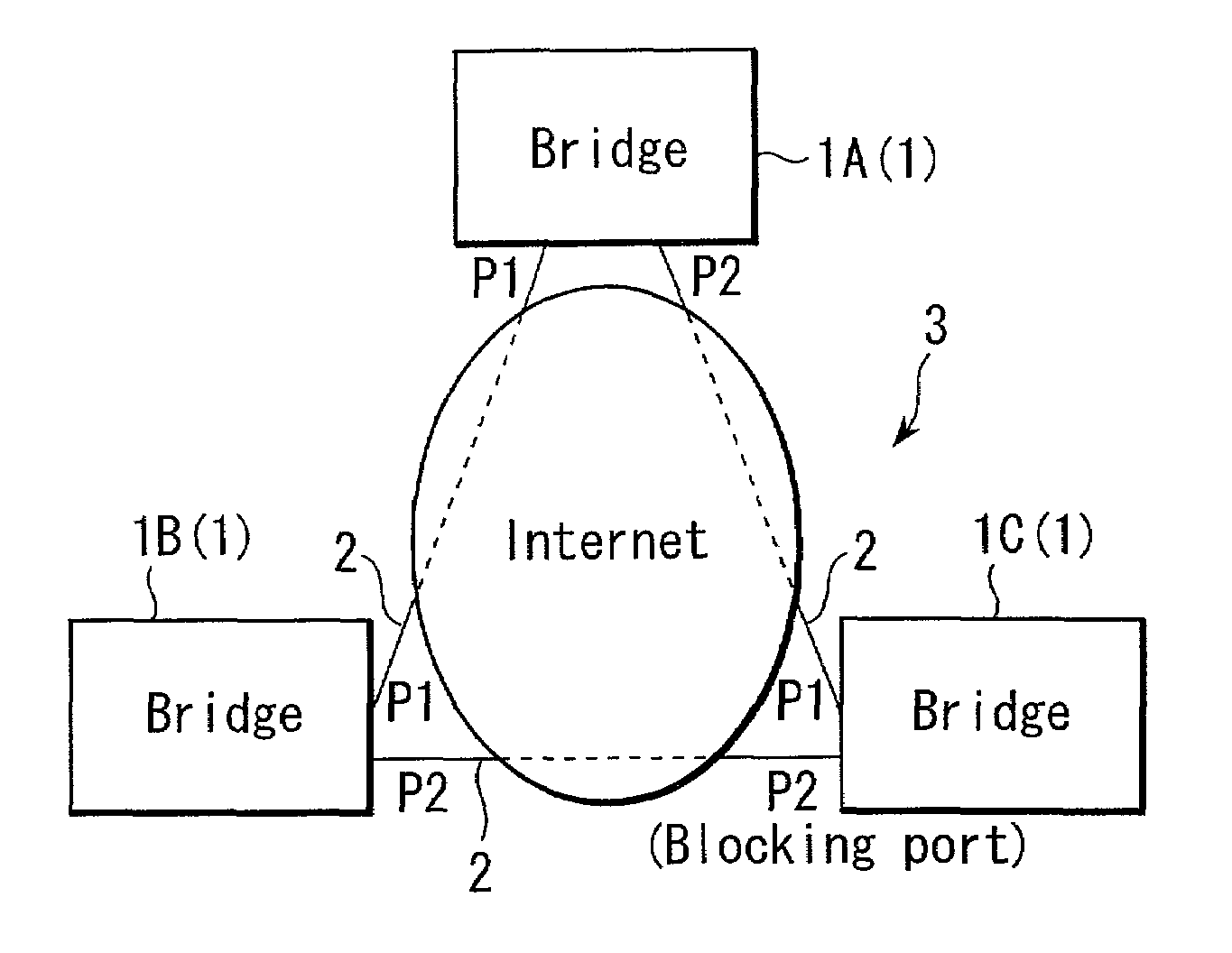
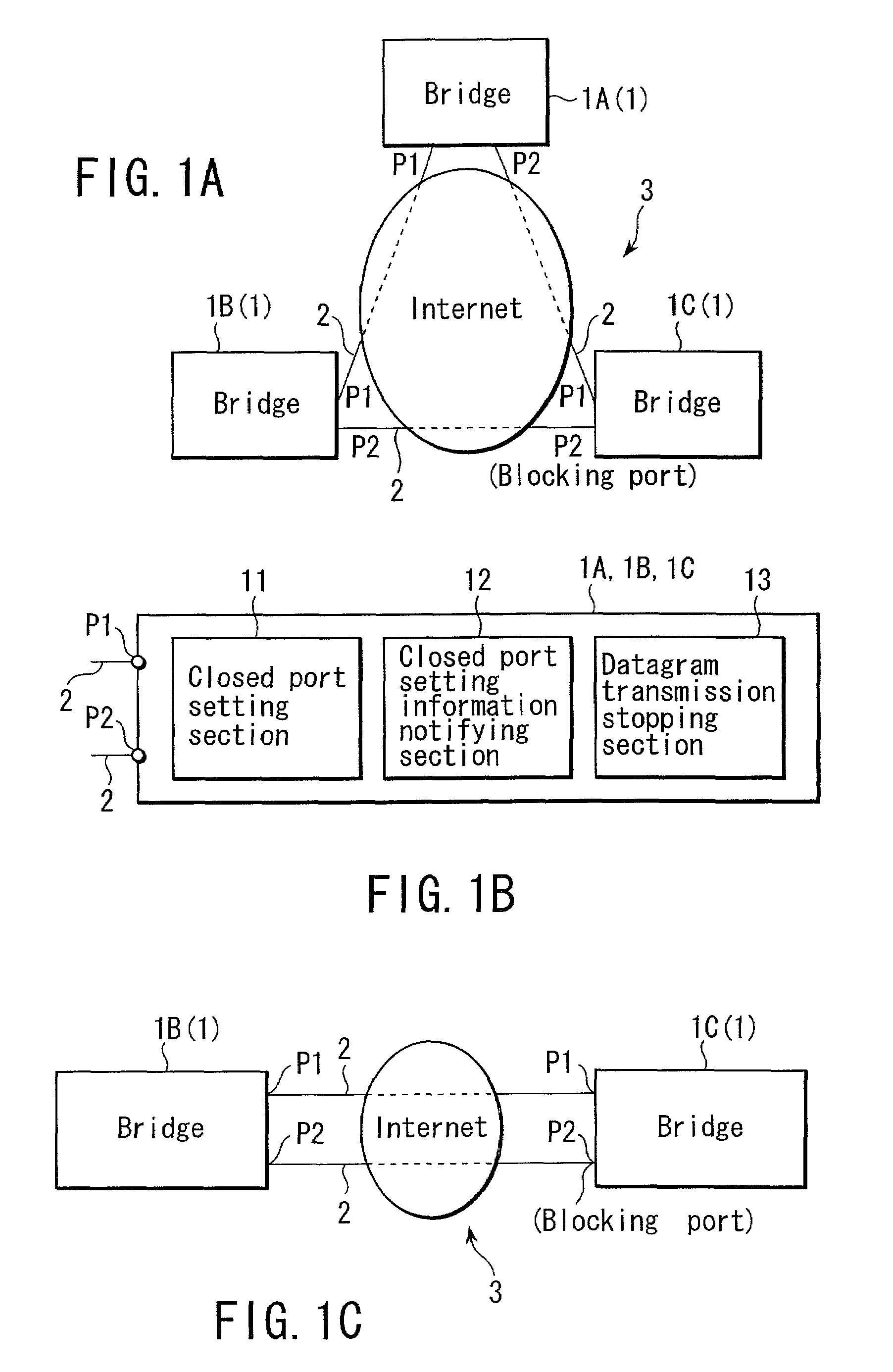
[0147]In one embodiment shown in FIG. 1A, there is configured a network 3 in which three bridges 1 (1A, 1B, 1C) being communication relay devices are connected at both ends of a line 2, the network including a redundancy channel.

[0148]In this network 3, the spanning tree protocol as described previously is used for determining a channel.

[0149]In addition, in the network 3 shown in FIG. 1, as t...


PUM


Abstract

A communication relay device with a redundancy function for a line in a network under a WAN environment is connected to another, having a one-to-one relationship at both ends of each line by first and second ports to configure a redundancy channel between lines. A closed port setting section sets one of the ports as a closed port, thereby configuring a network free of a loop between the respective lines. A closed port setting information notifying section notifies a counterpart communication relay device connected to the one port, via the one port, of closed port setting notifying information for notifying that one of the ports has been set as a closed port. A datagram transmission stopping section stops transmission of a datagram from a port of its own connected to the one port set as the closed port when receiving the closed port setting notification information as the counterpart communication relay device.

Description

CROSS-REFERENCE TO RELATED APPLICATIONS[0001]This application is based upon and claims the benefit of priority from the prior Japanese Patent Applications No. 2001-190136, filed Jun. 22, 2001, the entire contents of which are incorporated herein by reference.BACKGROUND OF THE INVENTION[0002]1. Field of the Invention[0003]The present invention relates to a communication relay device with a redundancy function for a line in a network in accordance with a WAN environment, and a communication system using the relay device. More particularly, the present invention relates to a communication relay device with a redundancy function for a line in a network in a WAN environment including a redundancy channel in which a plurality of communication relay devices such as a bridge, a two-layer switch, and a multi-layer switch are connected in a one-to-one manner at both ends of the line, and a communication system using the relay device.[0004]2. Description of the Related Art[0005]A description w...

Claims


Application Information

Patent Timeline
Patent Type & Authority Patents(United States)
IPC IPC(8): H04L12/28H04L12/46H04L45/24H04L45/18
CPCH04L12/2854
Inventor HIGASHIYAMA, MITSURU
Owner ANRITSU CORP
Learn More