Vacuum cleaning head

Active Publication Date: 2008-10-28
DYSON TECH LTD
View PDF14 Cites 17 Cited by
  • Summary
  • Abstract
  • Description
  • Claims
  • Application Information

AI Technical Summary

Benefits of technology

[0005]The present invention seeks to improv

Problems solved by technology

‘Dirty air’ turbine-driven tools have a disadvantage in that they can easily become fouled by the dirty airflow.
They also have a disadvantage in that the speed at which the turbine rotates can increase quite rapidly when the tool is lifted from a surface.
‘Clean air’ turbine-driven tools can also suffer from an increase in speed under certain conditions.
A full or partial blockage of the airflow path thr

Method used


Image

  • Vacuum cleaning head
  • Vacuum cleaning head
  • Vacuum cleaning head

Examples


Embodiment Construction

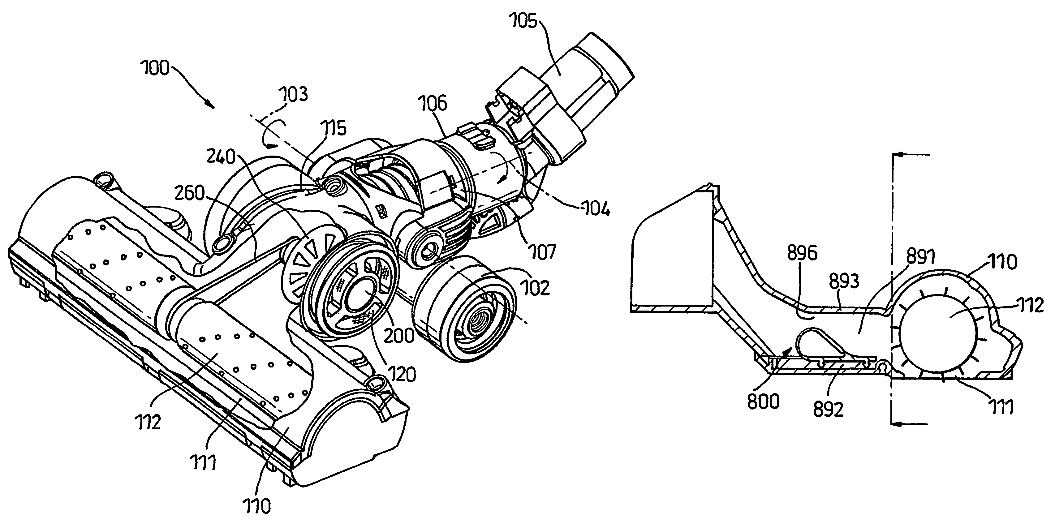
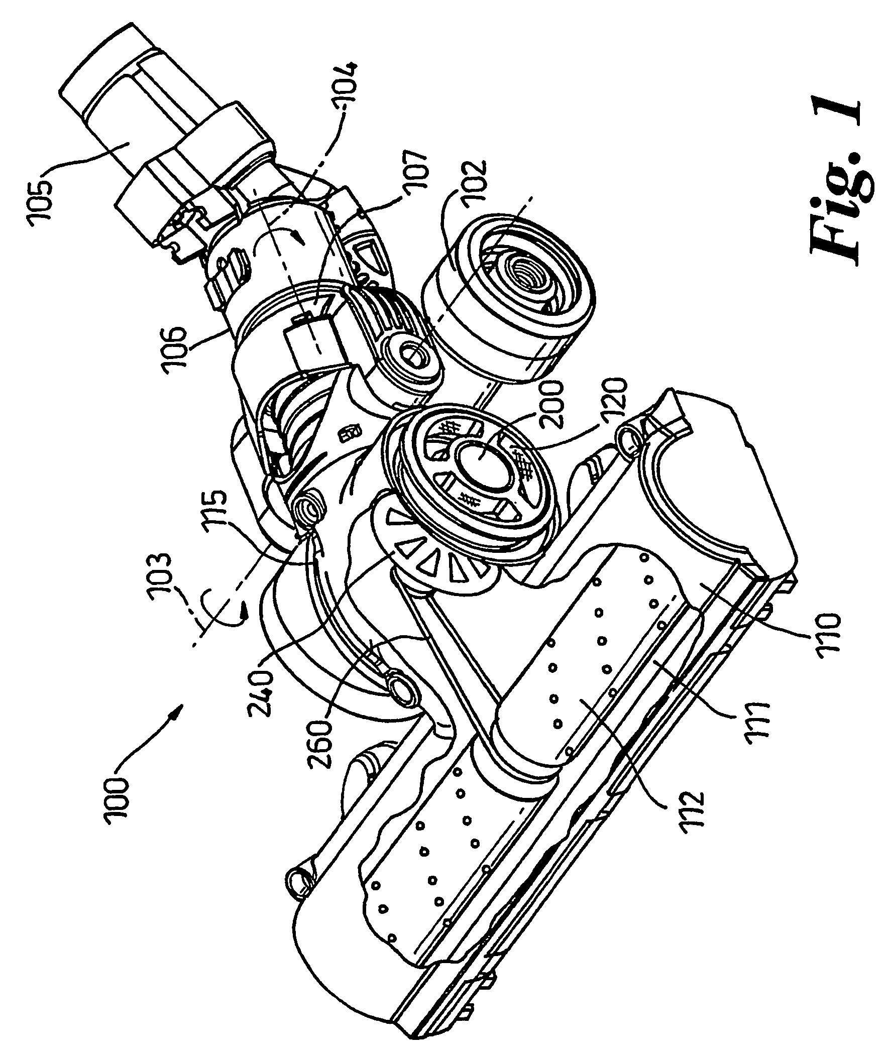
[0021]FIG. 1 shows an embodiment of the tool in the form of a tool 100 which can be fitted to the end of a wand or hose of a vacuum cleaner.

[0022]The main housing of the tool defines a chamber 110 for the brush bar 112, a chamber 115 for the turbine 240 and flow ducts between these parts. The forward, generally hood-shaped, part 110 of the housing and a lower plate together define a chamber for housing the brush bar. The brush bar comprises two brush bars 112 of equal size which are supported, cantilever fashion, from a part of the driving mechanism positioned in the centre of the chamber 110. The lower plate has a large aperture 111 through which the bristles of the brush bars 112 can protrude to agitate the floor surface. The lower plate is fixed to the remainder of the housing by quick release (e.g. quarter turn) fasteners so that the plate can be removed to gain access to the brush bars 112.

[0023]Two wheels 102 are rotatably mounted to the rear part of the housing to allow the t...


PUM


Abstract

A restricting device is positioned in the flow duct leading from the main inlet to the cleaning head of a vacuum cleaner and is movable between a restrictive position, in which it serves to restrict the cross-section of the discharge outlet, and an open position, in which it restricts the cross-section of the discharge outlet to a lesser extent. The restricting device is movable by the passage of debris along the flow duct.

Description

FIELD OF THE INVENTION[0001]This invention relates to a vacuum cleaning head which can be used with, or form part of, a vacuum cleaner.BACKGROUND OF THE INVENTION[0002]Vacuum cleaners are generally supplied with a range of tools for dealing with specific types of cleaning. The tools include a floor tool for general on-the-floor cleaning. It is well-known to provide a floor tool in which a brush bar is rotatably mounted within a suction opening on the underside of the tool, with the brush bar being driven by an air turbine. The brush bar serves to agitate the floor surface beneath the tool so as to release dirt, dust, hair, fluff and other debris from the floor surface where it can then be carried by the flow of air to the vacuum cleaner itself. The turbine can be driven solely by ‘dirty’ air which enters the tool via the suction opening, it can be driven solely by ‘clean’ air which enters the tool via a dedicated inlet which is separate from the main suction opening, or it can be dr...

Claims


Application Information

Patent Timeline
IPC IPC(8): A47L9/04
CPCA47L9/0416A47L9/04
Inventor SMITH, DAVID BENJAMIN
Owner DYSON TECH LTD
Why Eureka
Try Eureka