Synchronized compound archery bow

a compound archery and bow technology, applied in the field of compound archery bows, can solve the problems of insufficient force application to the opposite side of the mounting axle of the pulley assembly, time-consuming and technical adjustment of the rigging, and the effort to re-tune the bow requires rigging adjustments and adjustments, and achieves the effect of evenly discharging the cable tension for

Inactive Publication Date: 2008-10-28
BOWTECH INC
View PDF13 Cites 101 Cited by
  • Summary
  • Abstract
  • Description
  • Claims
  • Application Information

AI Technical Summary

Benefits of technology

[0019]Unlike the cross coupling arrangement suggested by the '425 patent, the dynamic anchoring system of this invention is associated with means for redistributing the forces applied to opposite sides of the pulley assemblies at all rest and drawn positions of the bowstring. One such means is to mount duplicate synchronizing anchor components on opposite sides of each pulley assembly. The synchronizing ends of each cable may then be attached through a “Y harness,” or equivalent force dividing structure, to both of the duplicate components, thereby evenly distributing the cable tension forces at that end o

Problems solved by technology

A troublesome characteristic of the rigging systems offered by commercial compound bows is the inherently unequal application of force to opposite sides of the mounting axles of the pulley assemblies as the bowstring is drawn.
As a general matter, riggings that position all of the cables to one side of the bowstring inevitably apply cable forces to the same side of the string groove

Method used


Image

  • Synchronized compound archery bow
  • Synchronized compound archery bow
  • Synchronized compound archery bow

Examples


Embodiment Construction

)

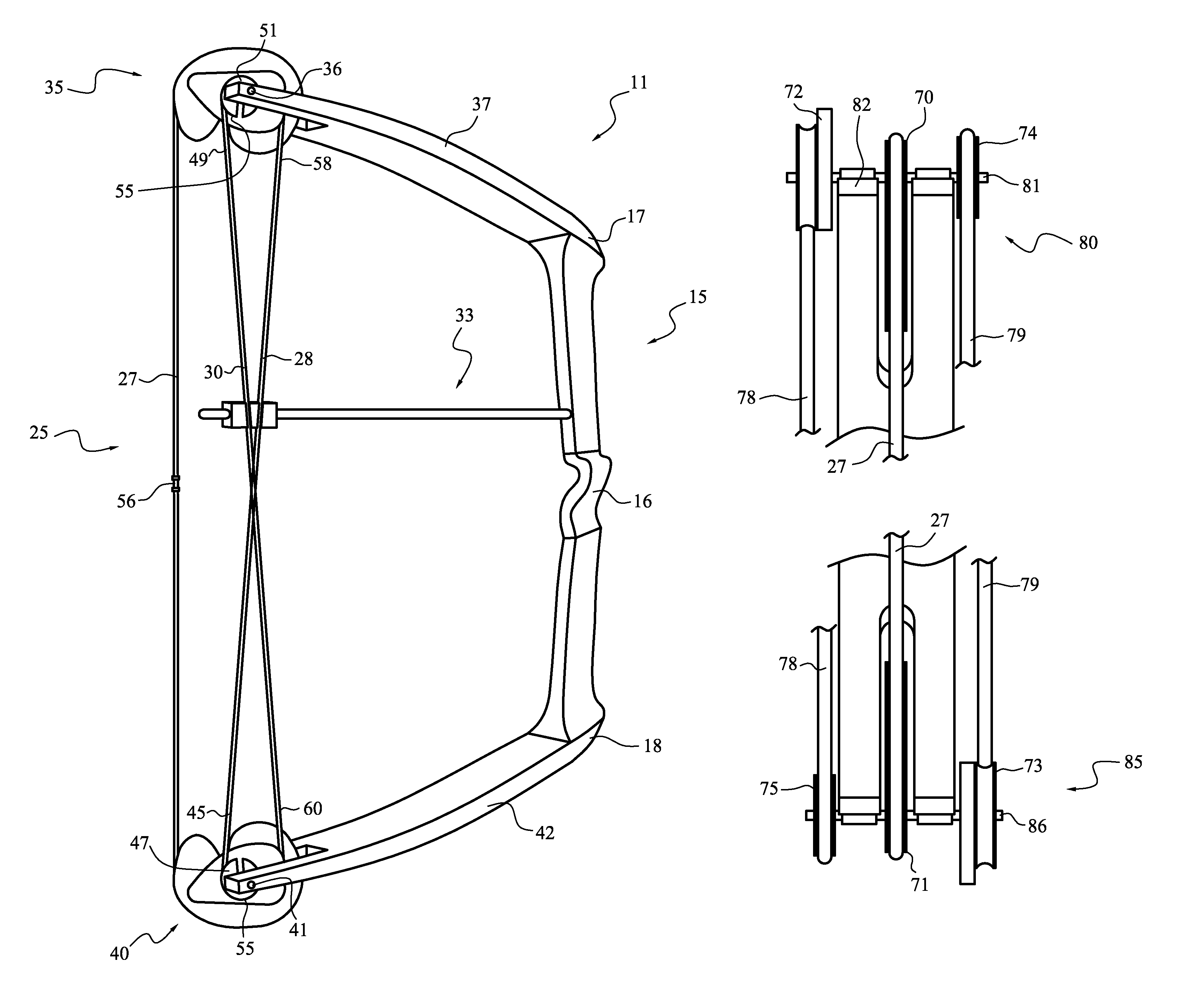
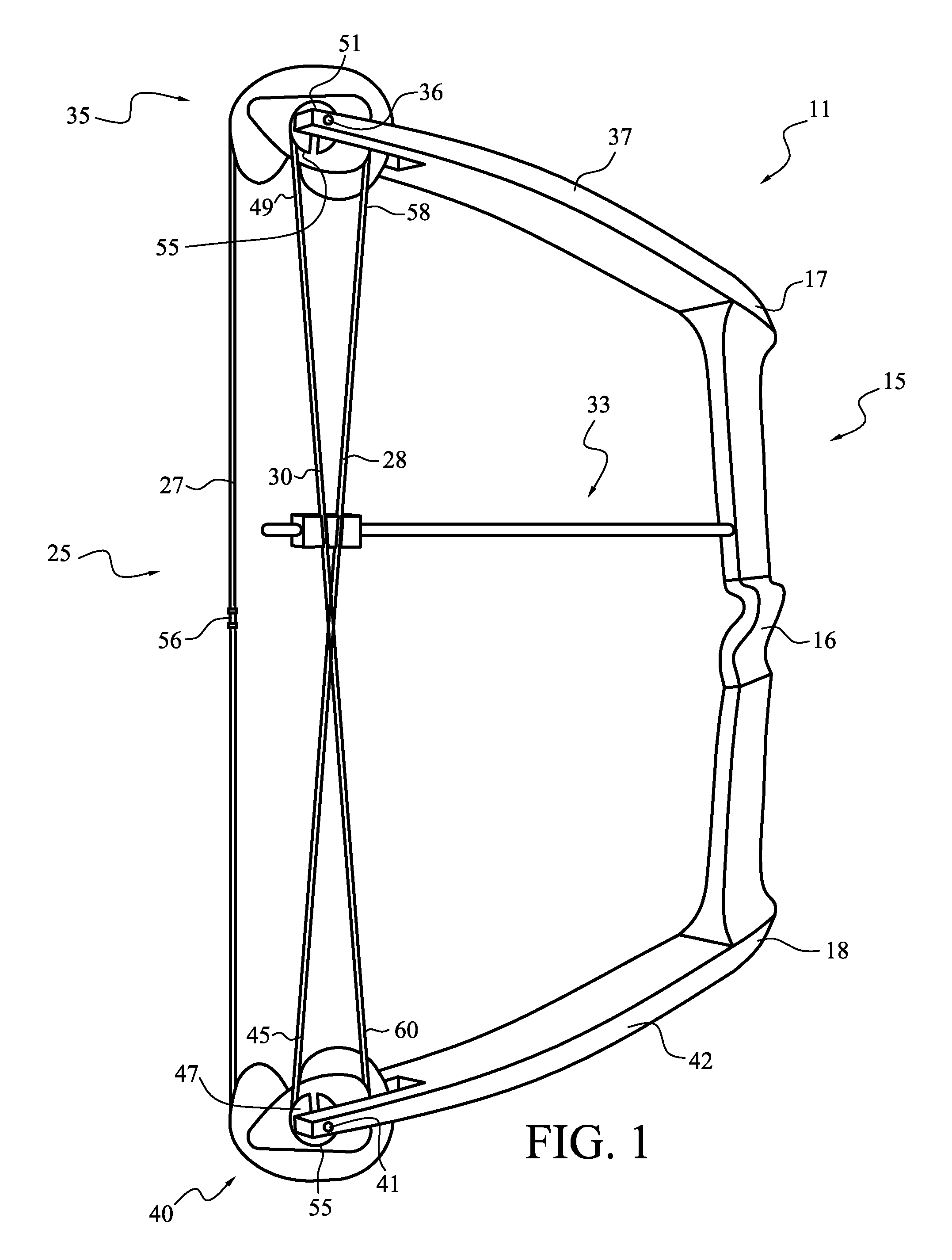
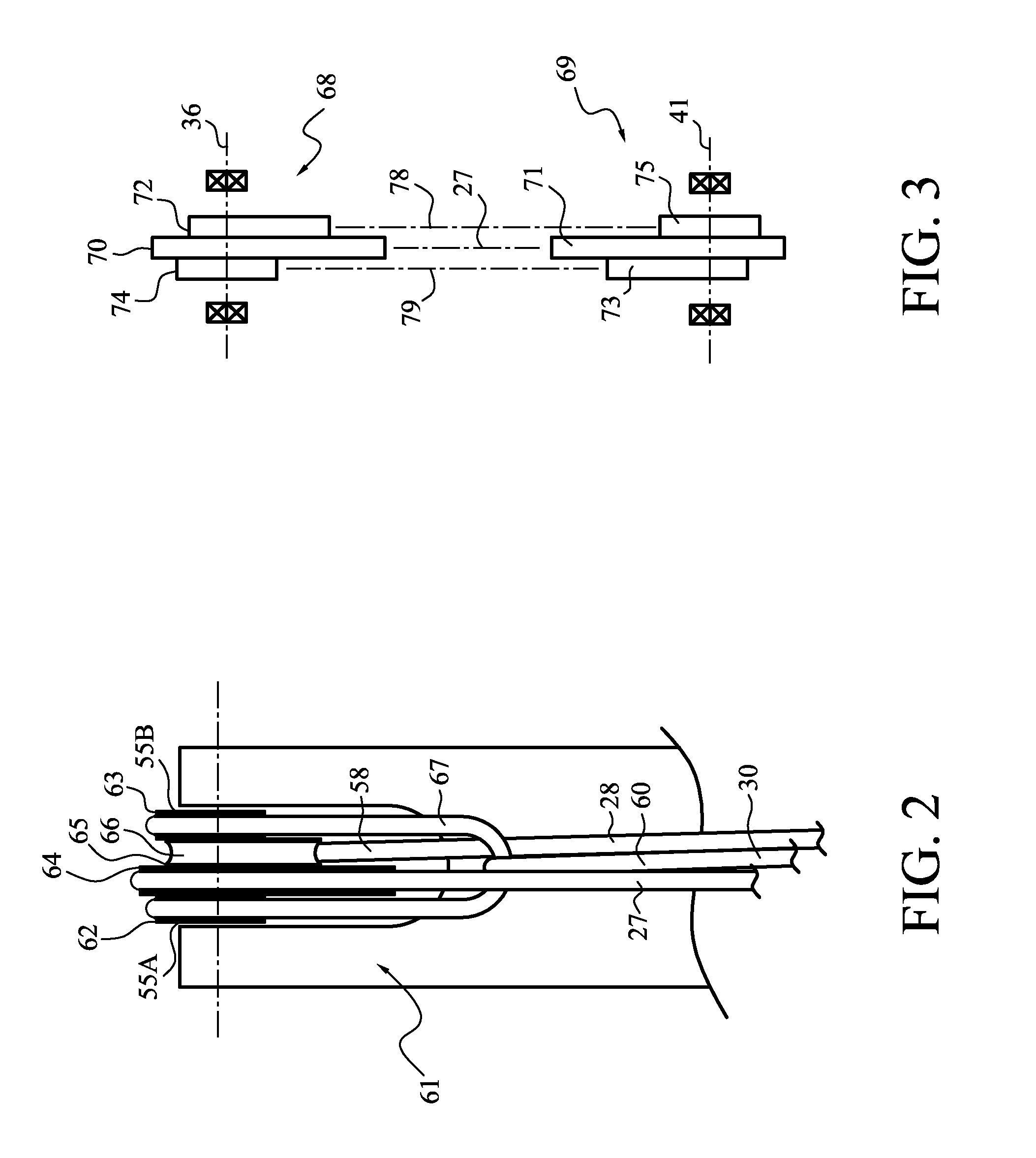
[0027]The compound bow, generally 11, illustrated by FIG. 1, is of generally conventional construction. It includes a handle riser component, generally 15, with a grip 16, an upper end 17 and a lower end 18. The rigging, generally 25, includes a bowstring 27, and two synchronizing cables 28, 30. The cables 28, 30 are held away from the operating plane of the bowstring 27 by a cable guard assembly, generally 33. An upper pulley assembly, generally 35, is mounted on a pivot axle 36 at the tip of an upper limb 37. A lower pulley assembly, generally 40 is similarly mounted on a pivot axle 41 at the tip of a lower limb 42. The rigging of pulley assembly 35 is arranged generally conventionally, except that the synchronizing end 45 of the cable 28 is coupled to the pulley assembly 40 through a synchronizing anchor component 47. Similarly, the synchronizing end 49 of the cable 30 is coupled to the pulley assembly 35 through a synchronizing anchor component 51. This “cross coupling” configu...


PUM


Abstract

A rigging structure for a compound archery bow includes first and second pulley assemblies, pivotally mounted on axles at tips of corresponding first and second limbs of a compound bow and interconnected by cables. Each pulley assembly includes a dynamic synchronizing component, and the rigging preferably also includes means for avoiding the usual leaning moment imposed upon the pulley assemblies by the cables of conventional riggings.

Description

BACKGROUND[0001]1. Field of the Invention[0002]This invention relates to compound archery bows. It is particularly directed to an improved rigging system for such bows.[0003]2. State of the Art[0004]Compound archery bows commonly carry assemblies of pulley members (usually called “eccentrics” or “cams”) eccentrically mounted on axles in association with respective bow limbs. These limbs extend in opposite directions from a grip (usually comprising a central portion of a handle riser). The rigging for compound bows includes a bowstring trained around the pulley members of the system, the string being received by grooves or other functionally equivalent features at the perimeters of the pulleys. The eccentric pulley assemblies are conventionally mounted to rotate (pivot) on an axle within a notch at the distal end of the limb, or within a bracket structure carried by the limb tip. The eccentrics include one or more pivot holes substantially offset from center, whereby to provide for a...

Claims


Application Information

Patent Timeline
IPC IPC(8): F41B5/10
CPCF41B5/10F41B5/105
Inventor LARSON, MARLOW W.
Owner BOWTECH INC
Why Eureka
Try Eureka