Cutlery receptacle

a technology for receptacles and cutting boards, which is applied in the field of receptacles, can solve the problems that none of these prior art patents have solved the needs of this art, and achieve the effects of preventing blade horizontal displacemen

Inactive Publication Date: 2008-10-28
NELSON GARY W
View PDF26 Cites 6 Cited by
  • Summary
  • Abstract
  • Description
  • Claims
  • Application Information

AI Technical Summary

Benefits of technology

[0037]In a more specific embodiment of the invention, a top coupling member is secured to the wall member extending substantially perpendicular and above the base for contacting the blade to prevent vertical displacement of the blade. A front coupling member is secured to the wall member extending substantially perpendicular and above the base for contacting the blade to prevent horizontal displacement of the blade. An arm member is secured to the coupling member extending substantially parallel to the wall member and above the base. A rear coupling member is secured between the wall member and the arm member for contacting the blade heel to prevent horizontal displacement of the blade

Problems solved by technology

Although the aforementioned prior art have contributed to the development of the art of cutlery receptacles, none of these prior art patents have solved the needs of this art.

Method used


Image

  • Cutlery receptacle
  • Cutlery receptacle
  • Cutlery receptacle

Examples


first embodiment

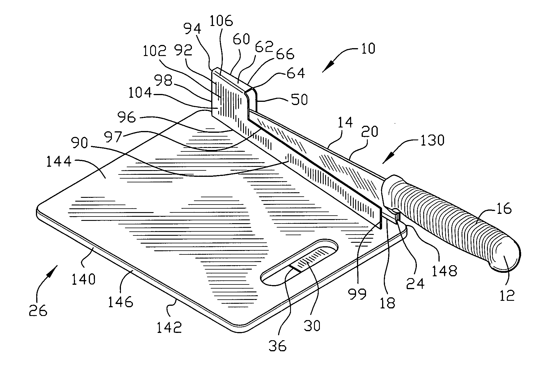
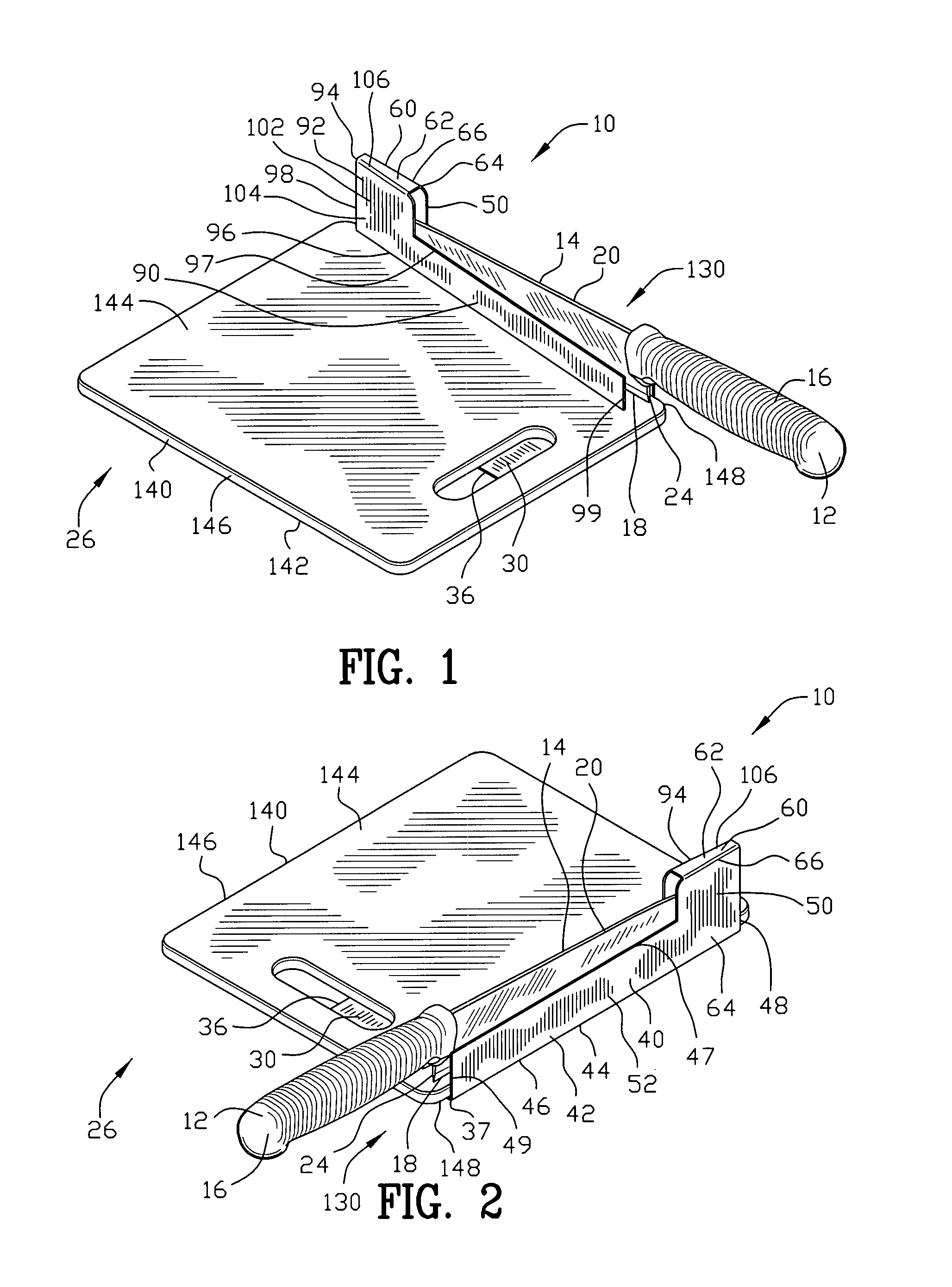
[0083]FIGS. 1-10 are various views of a receptacle 10 for retaining a cutlery instrument 12. As best seen in FIG. 10 the cutlery instrument 12 includes a blade 14 and a handle 16. The blade 14 further includes a blade edge 18, a blade spine 20, a blade tip 22 and a blade heel 24.

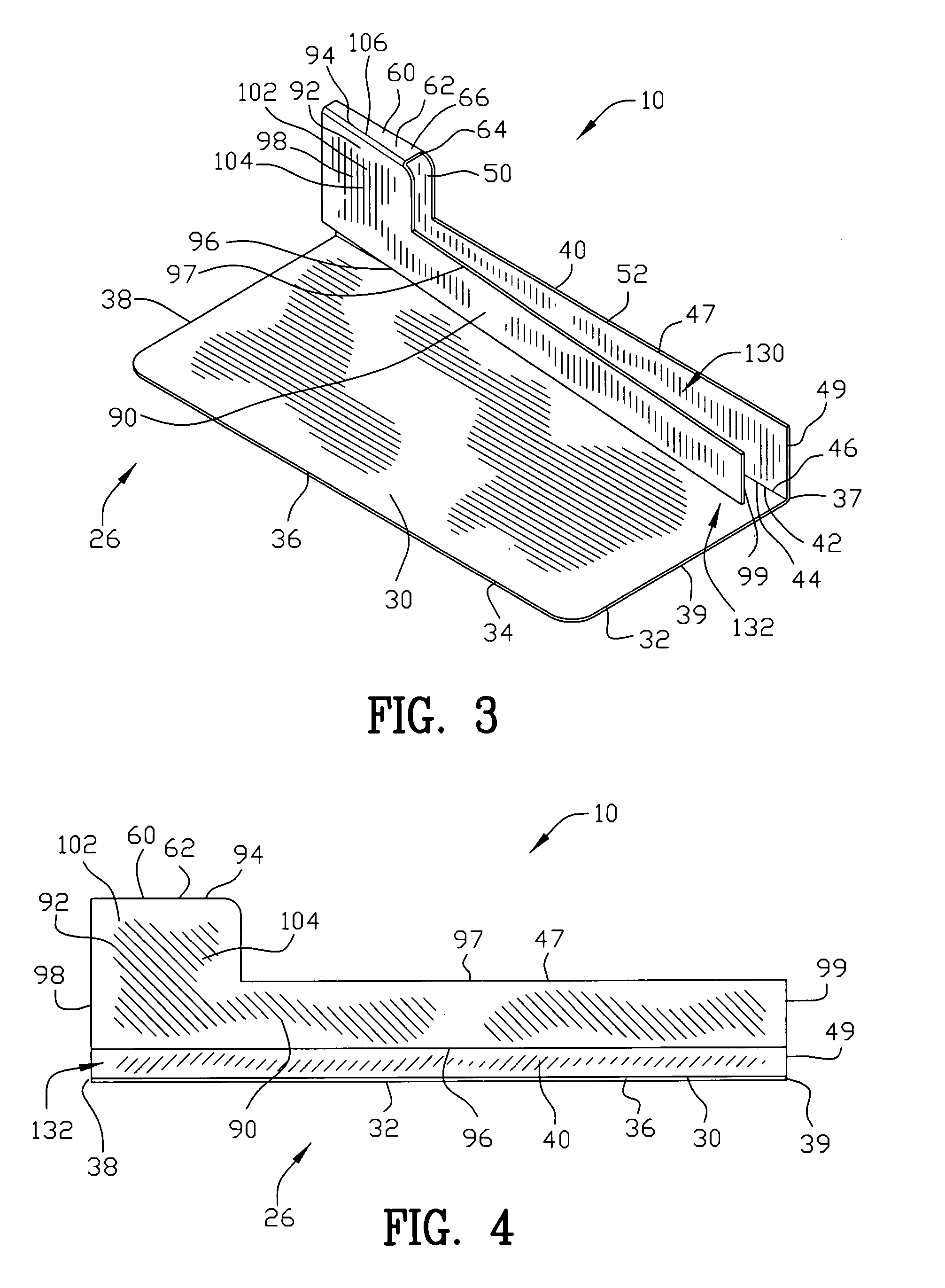
[0084]The receptacle 10 comprises a base 30 having a base support surface 32 and a base engaging surface 34. The base 30 is shown having a rectangular shape defined by a first edge 36, second edge 37, third edge 38 and fourth edge 39. However, the base 30 may include other geometric shapes and dimensions. The base support surface 32 provides a surface for resting on an ambient surface 26. The base support surface 32 may be permanently mounted to an ambient horizontal surface 26 by a suitable mechanical fastener or an adhesive fastener. Alternatively, the base support surface 32 may merely rest upon the ambient surface 26 without any mechanical fastener or an adhesive fastener.

[0085]A wall member 40 is secure...

second embodiment

[0089]In the receptacle 10 illustrated in FIGS. 11-14, the coupling member 60 includes a front coupling member 72. The front coupling member 72 is secured to the wall member 40. The front coupling member 72 may be secured to the third edge 48 of the wall member 40. If the wall extender 50 is included to form the L-shaped wall member 52, the front coupling member 72 may be secured to the wall extender 50. The wall member 40 and the front coupling member 72 may be constructed of an integral one piece unit 74 including a ninety degree bend 76 positioned between the wall member 40 and the front coupling member 72 for maintaining the front coupling member 72 substantially perpendicular to the wall member 40. The integral one piece unit 74 including the ninety degree bend 76 is constructed from a metallic material by bending sheet metal, metallic material by casting molten metal, polymeric material by injection molding, or other materials and forms of manufacturing. As best seen in FIGS. ...

third embodiment

[0090]In the receptacle 10 illustrated in FIGS. 15-16, the coupling member 60 includes both the top coupling member 62 and the front coupling member 72. Both the top coupling member 62 and the front coupling member 72 are secured to the wall member 40. The top coupling member 62 may be secured to the second edge 47 of the wall member 40 and the front coupling member 72 may be secured to the third edge 48 of the wall member 40. If the wall extender 50 is included to form the L-shaped wall member 52, the top coupling member 62 and the front coupling member 72 may be secured to the wall extender 50. The wall member 40, the top coupling member 62 and the front coupling member 72 may be constructed of an integral one piece unit 80 including a first ninety degree bend 66 and a second ninety degree bend 76 positioned between the wall member 40 and the top coupling member 62 and the front coupling member 72 respectively. The integral one piece unit 80 including the first and second ninety d...


PUM


Abstract

An improved receptacle is disclosed for retaining a cutlery instrument, the cutlery instrument has a blade and a handle. The receptacle comprises a base having a base support surface and a base engaging surface. A wall member is secured to the base engaging surface extending substantially perpendicular from said base. A coupling member is secured to the wall member extending substantially parallel and above said base. An arm member is secured to the coupling member extending substantially parallel to the wall member and above the base. A slit is defined between the wall member and the arm member for receiving and maintaining the blade of the cutlery instrument in a static position. A slot is defined between the arm member and the base engaging surface for exposing the wall member.

Description

CROSS-REFERENCE TO RELATED APPLICATIONS[0001]This application claims benefit of United States Patent Provisional application Ser. No. 60 / 838,966 filed Aug. 21, 2006. All subject matter set forth in provisional application Ser. No. 60 / 838,966 is hereby incorporated by reference into the present application as if fully set forth herein.BACKGROUND OF THE INVENTION[0002]1. Field of the Invention[0003]This invention relates to receptacles and more particularly to an improved receptacle for retaining a cutlery instrument.[0004]2. Background of the Invention[0005]Various types of cutlery receptacles have been proposed by the prior art. Cutlery receptacles retain a cutlery instrument in a static position for storage. When a cutlery instrument is to be utilized the cutlery instrument is withdrawn from the cutlery receptacle by an individual. Cutlery receptacles can be beneficial by providing efficient and convenient storage for cutlery instruments.[0006]A cutlery instrument may include one o...

Claims


Application Information

Patent Timeline
Patent Type & Authority Patents(United States)
IPC IPC(8): B65D1/34
CPCA47G21/14A47J47/005A47J47/16
Inventor NELSON, GARY W.
Owner NELSON GARY W
Why Eureka
Try Eureka