
Electric connector having segmented center contact member

a contact member and electric connector technology, applied in the direction of connection contact member material, coupling device details, coupling device connection, etc., can solve the problems of large amount of signal loss or energy leakage, etc., to prevent the gain from quickly decaying, excellent high frequency impedance matching

Inactive Publication Date: 2008-10-28
JOYMAX ELECTRONICS CO LTD
View PDF6 Cites 28 Cited by
  • Summary
  • Abstract
  • Description
  • Claims
  • Application Information

AI Technical Summary

Benefits of technology

[0009]The primary objective of the present invention is to provide an electric connector including an excellent high frequency impedance matching for preventing the gain from quickly decay and for allowing the electric connector to be used for a wide range of frequencies.
[0010]In accordance with one aspect of the invention, there is provided an electric connector comprising a housing including a chamber formed therein, and including two end portions, two couplers attached and engaged with the end portions of the housing respectively, a center contact member disposed in the chamber of the housing and extended in the couplers, at least one insulator disposed in the housing for insulating and spacing the center contact member from the housing and the couplers and for preventing the center contact member from electrically contacting with the housing and the couplers, and a lightening discharger disposed in the chamber of the housing and coupled to the center contact member, and the center contact member includes a first contact segment and at least one second contact segment each having an outer diameter different from an outer diameter of the center contact member for increasing the impedance matching and for preventing the signal loss or the energy leakage or the gain loss from being occurred or generated in the electric connector.

Problems solved by technology

However, a large amount of signal loss or energy leakage may be occurred or generated in the typical coaxial cables, or the gain may quickly decay particularly in the higher frequencies such that the typical coaxial cables may not be used for a wide range of frequencies.

Method used


Image

  • Electric connector having segmented center contact member
  • Electric connector having segmented center contact member
  • Electric connector having segmented center contact member

Examples


Embodiment Construction

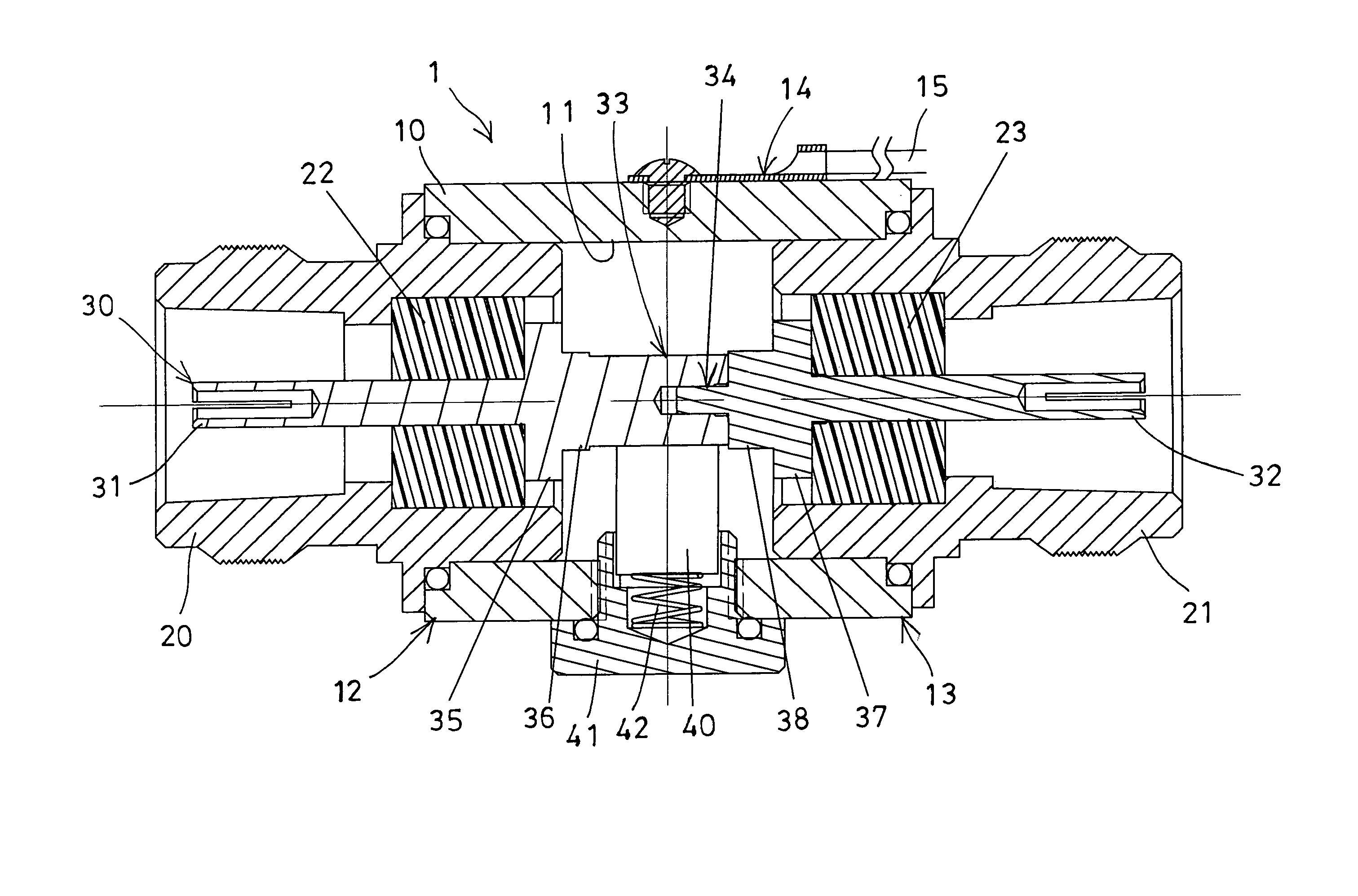
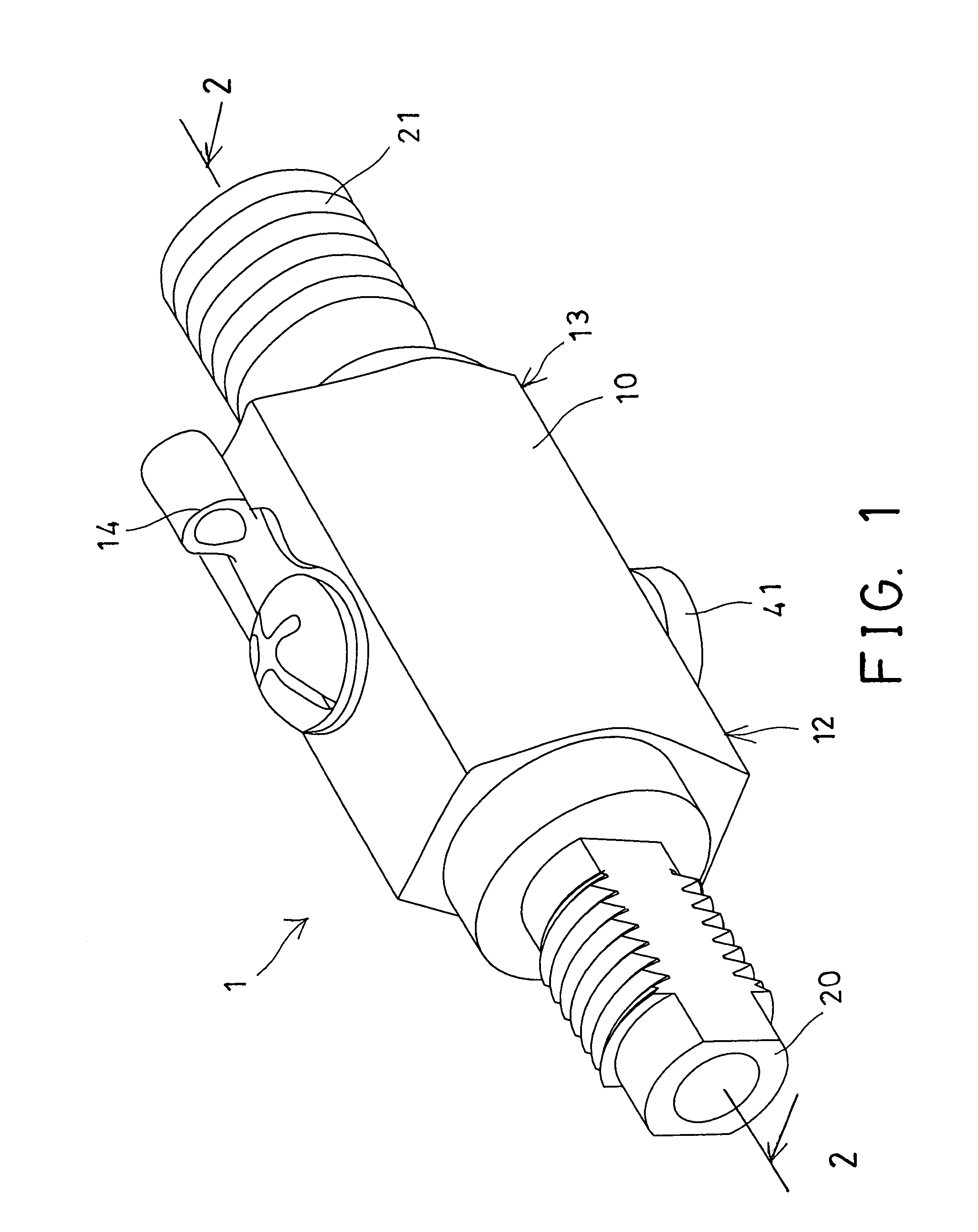
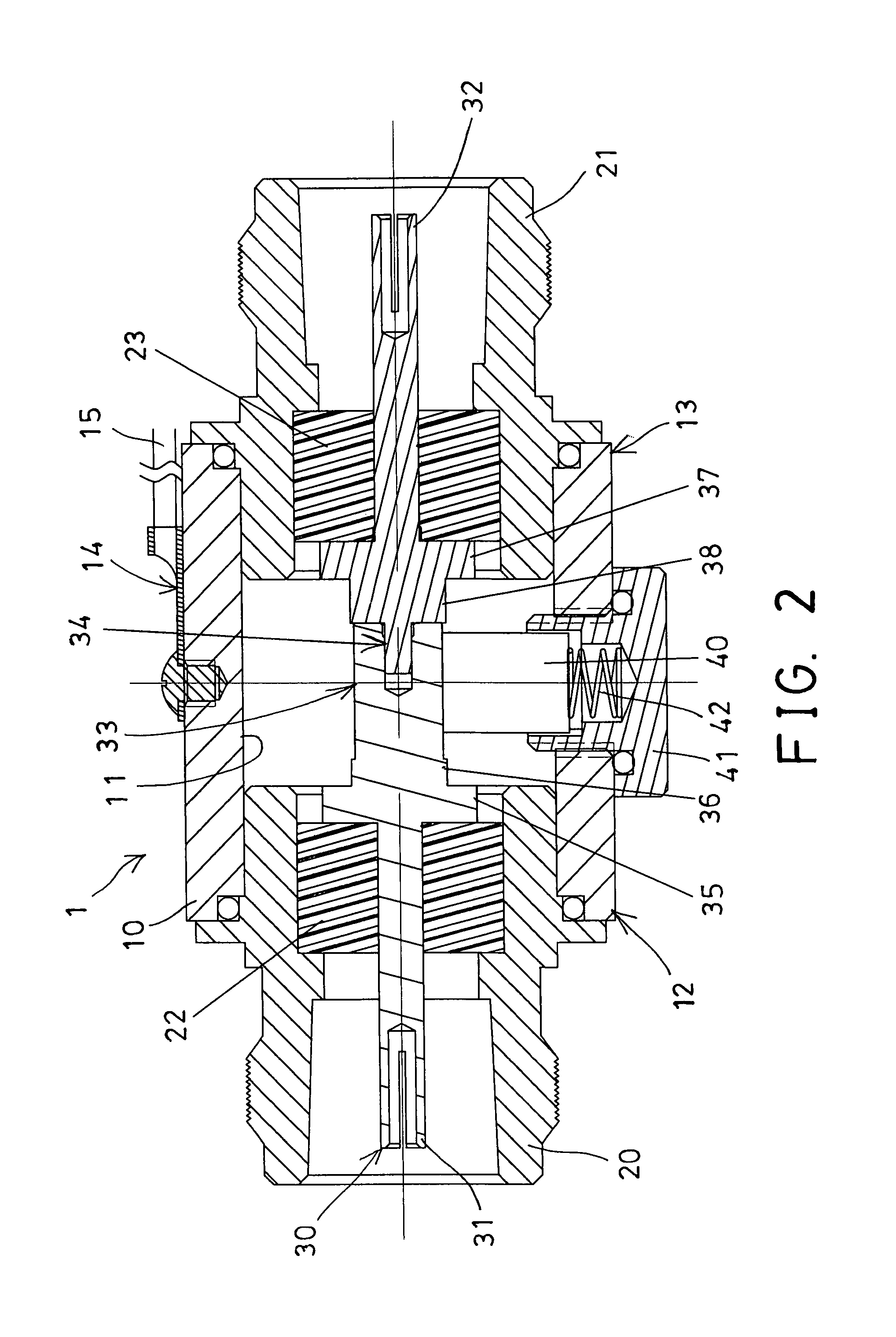
[0022]Referring to the drawings, and initially to FIGS. 1 and 2, an electric connector 1 in accordance with the present invention is provided for radio and television reception and similar transmission systems operating at radio frequencies and comprises an outer shell or housing 10 including a chamber 11 formed therein, and including two end portions 12, 13 for attaching or engaging with couplers 20, 21 respectively, and a connecting member 14 attached or coupled to the housing 10 for coupling or securing or engaging with an electric cable 15, such as a ground cable 15 and for such as grounding purposes.

[0023]As shown in FIG. 2, a center contact member 30 is disposed in the chamber 11 of the housing 10 and also extended or received or disposed in the couplers 20, 21, and one or more (such as two) spacers or insulators 22, 23 are disposed or engaged between the housing 10 or the couplers 20, 21 and the center contact member 30 for insulating or spacing the center contact member 30 f...


PUM


Abstract

An electric connector includes two couplers attached to two end portions of a housing, a center contact member disposed in the housing and the couplers, one or more insulators disposed in the housing for insulating and spacing the center contact member from the housing and the couplers and for preventing the center contact member from electrically contacting with the housing and the couplers, and a lightening discharger disposed in the housing and coupled to the center contact member, and the center contact member includes at least two contact segments having different diameter for increasing the impedance matching and for reducing the signal loss or energy leakage or gain loss.

Description

BACKGROUND OF THE INVENTION[0001]1. Field of the Invention[0002]The present invention relates to an electric connector, and more particularly to an electric connector including an excellent high frequency impedance matching for preventing the gain from quickly decay and for allowing the electric connector to be used for a wide range of frequencies.[0003]2. Description of the Prior Art[0004]Typical electric connectors comprise an outer shell and a coaxial cable or center contact member disposed in the outer shell for radio and television reception and similar transmission systems operating at radio frequencies.[0005]For example, U.S. Pat. No. 4,037,909 to Trompeter et al., U.S. Pat. No. 4,720,271 to Grange, and U.S. Pat. No. 5,183,411 to Yu disclose three of the typical coaxial cables each including a central contact engaged in an outer housing for telescopic current transmitting engagement with the shell of a mating connector, and for being operated at various radio frequencies for ...

Claims


Application Information

Patent Timeline
Patent Type & Authority Patents(United States)
IPC IPC(8): H01R9/05
CPCH01R9/0503H01R9/0512H01R9/0521H01R24/44H01R24/48H01R13/6666H01R2103/00
Inventor TSEN, YU CHING
Owner JOYMAX ELECTRONICS CO LTD
Learn More