High efficiency medical transducer with ergonomic shape and method of manufacture

a transducer and ergonomic technology, applied in the field of high-efficiency medical surgical transducers with ergonomically enhanced shapes, can solve the problems of inability to fully grasp the brain, enlarge the view of the delicate structure of the brain, and the disadvantageous length of the transducer/horn combination

Active Publication Date: 2008-10-28
MISONIX INC
View PDF14 Cites 77 Cited by
  • Summary
  • Abstract
  • Description
  • Claims
  • Application Information

AI Technical Summary

Benefits of technology

[0011]It is a further object of the present invention to provide an improved ultrasonic surgical instrument with concentric flow through a center of a handpiece and with no internal fluid passage joints which may leak and cause product failure.
[0018]Pursuant to a particular feature of the present invention, the stud projects a distance of between 2.50 and 3.25 inches from a front face of the electromechanical transducer. More particularly, the stud projects a distance of between 2.7 and 3.0 inches from the front face of the electromechanical transducer. In addition to a uniquely long length, the stud is formed with an especially thin wall, for instance, with a thickness between approximately 0.010 and 0.25 inch. The thin wall and the length of the stud enable the stud to function as a flexible element in damping vibrations of the electromechanical transducer.

Problems solved by technology

However, in applications such as open field brain surgery, such an embodiment is impractical since the doctor is using a microscope while operating, to enlarge the view of the delicate structures of the brain.
Here, the length of the transducer / horn combination may be disadvantageous, since the proximal end of the transducer will contact the microscope head and interfere with the ability of the surgeon to manipulate the tool for maximum efficacy.
As important, the transducer housing major diameter interferes with the surgeon's field of view of the operative site.
Several factors have limited the benefit of a bent transducer or probe.
This motion reduces the efficiency of the tip action and increases the energy loss in the transducer itself.
As a result, the transducer temperature rises, causing the surface to become too hot to touch.
Also, the transverse vibrations lead to large stresses in the vibratory elements which at higher amplitudes cause metal fatigue and probe fracture.
Because of these design problems, the designer will both limit the bend angle as well as reduce the maximum tip amplitude at which the device will be allowed to vibrate.
Both remedies reduce the efficacy of the operative procedure in that the harder, denser tumors require higher amplitudes and more power to ablate and remove.
The larger the unit, the heavier and more difficult it is to manipulate.
Since the electrical power required to ablate tissue and overcome the electromechanical losses in the handpiece is up to 70 watts, making a thinner handpiece that does not get hot during use is problematic due to the fact the crystal mass in a piezoelectric handpiece is reduced.
The power density will then rise, increasing power loss and waste heat generation.
Similar problems exist for magnetostrictive devices, although these can generally be thinner for given wattage output.
However, since magnetostrictive devices cannot easily accommodate a central aspiration port (one that is concentric with the long axis) tissue blockage can occur when aspirating tissue.
This is a major detriment.
This leads to less tactile feedback during the operation, fatigue and could in fact lead to damage of the hand upon long exposure.

Method used


Image

  • High efficiency medical transducer with ergonomic shape and method of manufacture
  • High efficiency medical transducer with ergonomic shape and method of manufacture
  • High efficiency medical transducer with ergonomic shape and method of manufacture

Examples


Embodiment Construction

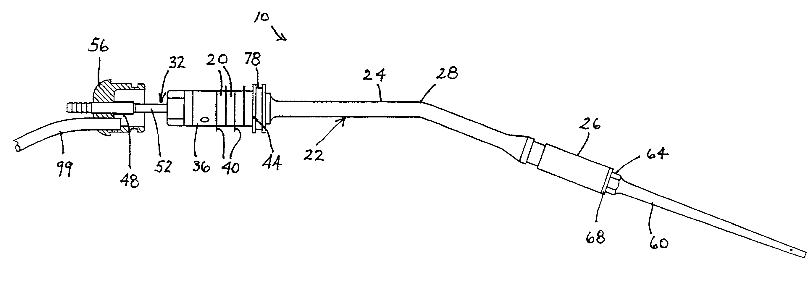
[0029]A piezoelectric transducer is disclosed herein which incorporates a plurality of features which in concert exhibit features desirable in the performance of delicate medical operations. In addition, the various features may have utility in and of themselves in different applications. The terminology used in discussing the transducer, an associated instrument assembly, and a method of manufacture will be that generally accepted in the art of ultrasound engineering. The term “fixedly connected” when used herein to describe the coupling of a stud to an inertial or damping mass refers to a connection which is such that the stud and the inertial or damping mass were fabricated as a single or unitary object. Thus, the connection is rigid and essentially irreversible.

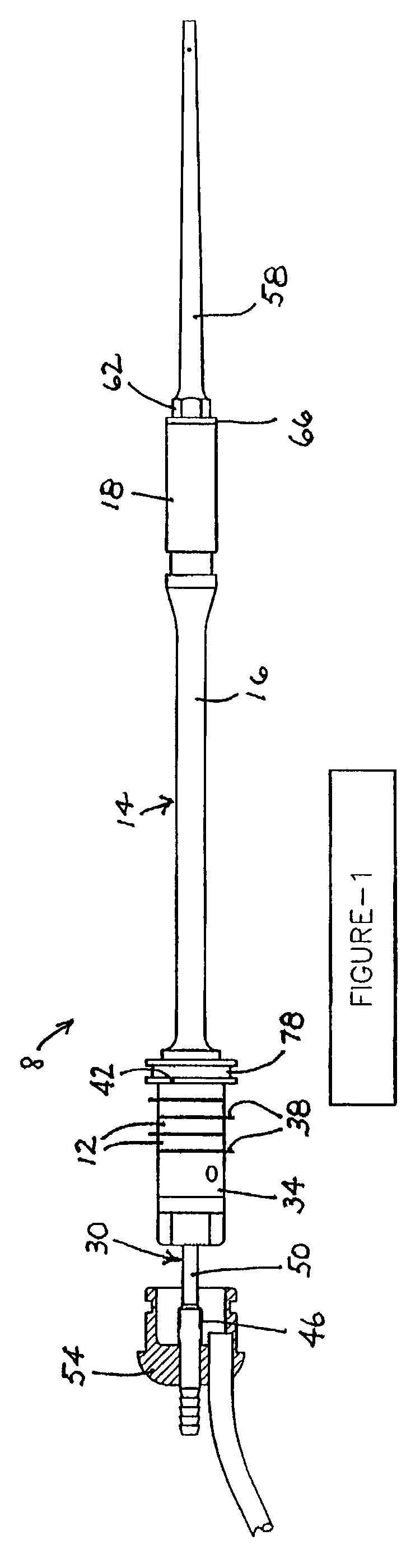
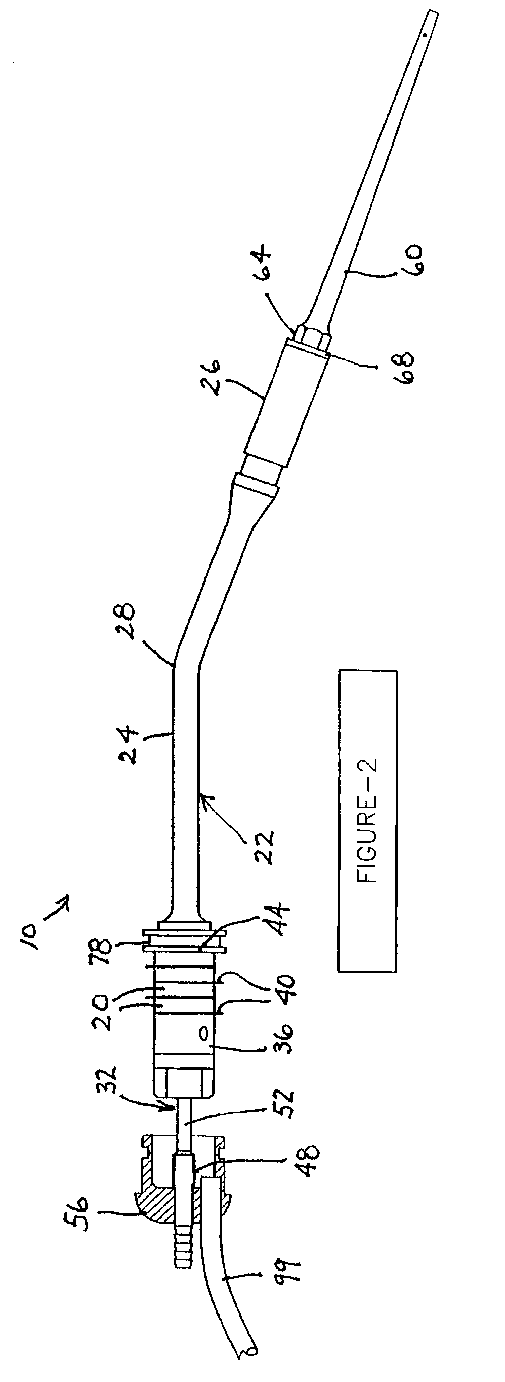
[0030]FIG. 1 shows a piezoelectric transducer 8 in a straight or unbent form, while FIG. 2 shows another transducer 10 in an angled or bent form. The transducer of FIG. 1 includes a stack of piezoelectric crystals 12 havi...


PUM


Abstract

A tranducer assembly for an ultrasonic surgical instrument includes a front driver having an elongate shaft in one direction and a stud extending in an opposite direction. An electromechanical transducer element is disposed around the stud. The transducer assembly also comprises a rear driver disposed around the stud on a side of the electromechanical transducer element opposite the front driver, the electromechanical transducer element being clamped between the front driver and the rear driver. An inertial or damping mass is fixedly connected to the stud at a point spaced from the rear driver. The stud is of length and thinness to act as a flexible vibration damping element.

Description

BACKGROUND OF THE INVENTION[0001]This invention relates to a high efficiency medical surgical transducer with an ergonomically enhanced shape. More particularly, this invention relates to a device that will transform electrical signals to mechanical vibrations to allow for ablation of tumors and other unwanted body tissues while allowing line of sight visualization of the operative sight by the surgeon.[0002]Over the past 30 years, several ultrasonic tools have been invented which can be used to ablate or cut tissue in surgery. Such devices are disclosed by Wuchinich et al. in U.S. Pat. No. 4,223,676 and Idemoto et al in U.S. Pat. No. 5,188,102.[0003]In practice, these surgical devices include a blunt tip hollow probe that vibrates at frequencies between 20 kc and 100 kc, with amplitudes up to 300 microns or more. Such devices ablate tissue by either producing cavitation bubbles which implode and disrupt cells, tissue compression and relaxation stresses (sometimes called the jackham...

Claims


Application Information

Patent Timeline
Patent Type & Authority Patents(United States)
IPC IPC(8): A61B8/00A61B8/12A61B8/14A61H1/00A61H1/02A61H5/00H01L41/00H02N2/00A61B18/00A61NA61N1/00A61N7/02
CPCA61B17/320068A61N7/02A61B2017/320088A61B2017/320084A61B2017/32007A61B2017/320089
Inventor NOVAK, THEODORE A. D.DARIAN, ALEXANDER L.VOIC, DANISOLA, SCOTTMANNA, RONALD R.
Owner MISONIX INC
Why Eureka
Try Eureka