Interspinal prosthesis

Inactive Publication Date: 2008-10-28
SYNTHES USA
View PDF14 Cites 259 Cited by
  • Summary
  • Abstract
  • Description
  • Claims
  • Application Information

AI Technical Summary

Benefits of technology

[0006]The invention is to provide a remedy here. It is therefore an object of the invention to provide an interspinal prosthesis, which can be implanted while t

Problems solved by technology

A disadvantage of this known prosthesis is the fact that the latter is in one piece, which makes the implantation more difficult, so that it is necessary to remove the supraspinal

Method used


Image

  • Interspinal prosthesis
  • Interspinal prosthesis
  • Interspinal prosthesis

Examples


Embodiment Construction

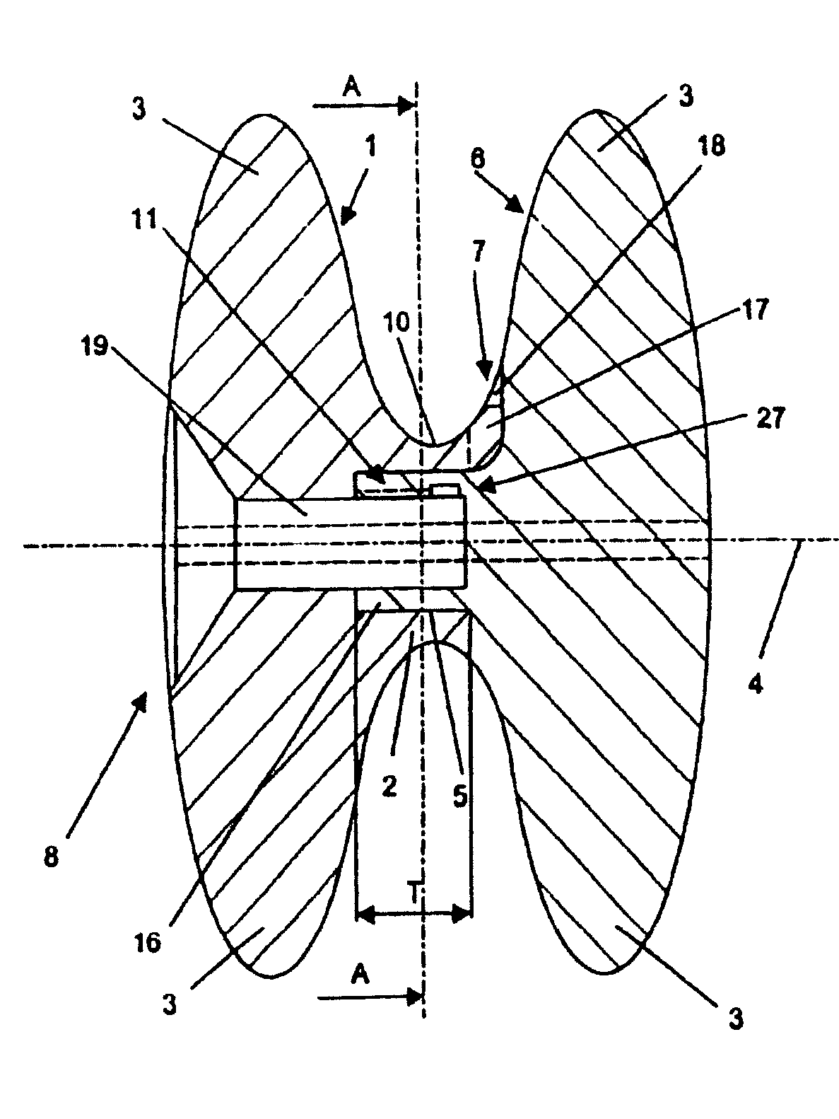
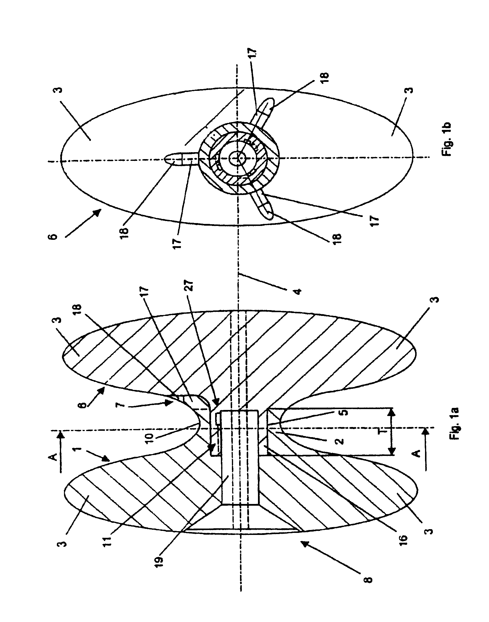
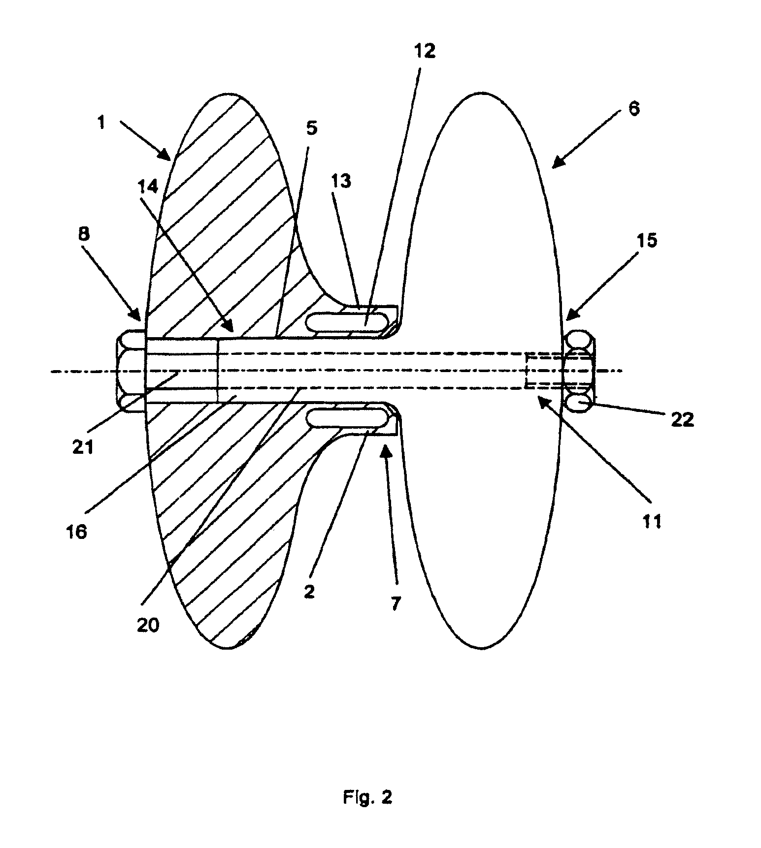
[0028]In FIG. 1, the interspinal prosthesis 1 with the counterpart 6 is shown in the assembled state. The central piece 2 of the prosthesis 1, with the inner end 7 of the prosthesis 1, adjoins the counterpart 6. At the outer end 8 of the prosthesis 1, the two processes 3 are disposed perpendicularly to the central axis 4 and diametrically opposite to one another. In the embodiment shown here, the processes 3 are constructed as halves of an ellipsoid body. The also radial and diametrically opposite to one another processes 3 of the counterpart 6 are disposed symmetrically to a plane, which is orthogonal to the central axis 4. Three radial cams 17, which are disposed symmetrically when viewed in the cross-section of the prosthesis 1 parallel to the central axis 4, protrude at the central piece 2 at the inner end 7 of the prosthesis and engage complementary grooves 18 at the counterpart 6, function as twisting safeguard between the prosthesis 1 and the counterpart 6. Coaxially with the...


PUM


Abstract

A prosthesis for use in maintaining an interspinal space is disclosed. The prosthesis may be provided as first and second substantially symmetrical halves. The first and second halves may each have a coupling portion and a process portion. The coupling portions allow the separate halves to be separately fit within the interspinal space and then connected to form a single prosthesis, eliminating the need for cutting connecting ligaments to allow insertion of the prosthesis. Various connection and locking arrangements are disclosed to maintain the halves engaged with each other and the interspinal space.

Description

CROSS-REFERENCE TO EARLIER-FILED APPLICATION[0001]This application is a continuation of co-pending PCT application serial number PCT / CH01 / 00509, filed Aug. 20, 2001, the entirety of which application is incorporated herein by reference thereto.BACKGROUND OF THE INVENTION[0002]The invention relates to an interspinal prosthesis with a central part having a central axis, which can be introduced into the interspinal space, an inner end and an outer end, as well as two processes, which arise at the outer end, the two processes extending radially and diametrically with respect to the central axis and which can be introduced into the space between the spinal processes of two adjacent vertebrae, a counterpart thereto as well as to a multi-part interspinal prosthesis combined therefrom.[0003]Such prostheses function as spacers for two adjacent vertebrae in the case of a defective disk, which would otherwise reduce the distance between the vertebrae. The stress on the facet joints is also rel...

Claims


Application Information

Patent Timeline
IPC IPC(8): A61F2/44A61B17/56A61B17/70
CPCA61B17/7068
Inventor MATHIEU, CLAUDELECHMANN, BEATPAVLOV, PAUL
Owner SYNTHES USA
Why Eureka
Try Eureka